
Related Manuals for UDI filters UdiMatic 785290

Summary of Contents for UDI filters UdiMatic 785290
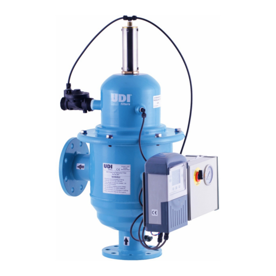
- Page 1 Manual UdiMatic Automatic Screen Filter Udimatic Installation- Operation- and Maintenance Manual UDI 12/2019...
-
Page 2: Table Of Contents
Manual UdiMatic INDEX 1 - Technical specification.................3 2 - Operating principle................5 3 - Installation procedures.................6 3.1 - Assembly prior to installation.......................6 3.2 - Filter installation...........................6 3.3 - Drain line installation..........................6 4 - First commissioning and routine start-up..........7 4.1 - Filter initial pre-sets..........................7 4.2 - First commissioning..........................7 4.3 - Start-up..............................7 5 - Filtron flushing controller ..............8... -
Page 3: Technical Specification
Manual UdiMatic 1 - TECHNICAL SPECIFICATION Screen Area & Maximum Flow Rates Model Inlet/Outlet diameter Max. Flow Rate Flush Flow Rate Screen Area inch m /h m /h 785290 1" (thr.) 2 - 3 7851B91 1½" 7851B92 2" 7851B93 3" 1450 7851E94 4"... - Page 4 Manual UdiMatic Type Unit 785290 7851B91 7851B92 7851B93 7851E94 7851964 785196 785198 Connection B inch 1" 1½" 2" 3" 4" 4" 6" 8" Capacity * m /h Flange (ISO 7005 PN10) Pitch C thread Holes 4 x Ø18 4 x Ø18 8 x Ø18 8 x Ø18 8 x Ø18...
-
Page 5: Operating Principle
Manual UdiMatic 2 - OPERATING PRINCIPLE A. Normal flow pattern Raw water enters the filter through the inlet port, passing through the fine screen (1) and out to the outlet port. The sediments stopped on the screen (1) create a "cake" of sediment. This "cake" improves filtration efficiency as it performs a finer filtration. -
Page 6: Installation Procedures
Manual UdiMatic 3 - INSTALLATION PROCEDURES 3.1 - Assembly prior to installation The filter is normally supplied fully assembled. Electrical connections will be done by authorized personnel only. Install the filter only in vertical position. 3.2 - Filter installation 1. For best results, the filter should be installed as near as possible to the system it is required to protect. However, if low filter inlet pressure is a concern, either before or during flushing, the filter may need to be installed closer to the pressure source. -
Page 7: First Commissioning And Routine Start-Up
Manual UdiMatic 4 - FIRST COMMISSIONING AND ROUTINE START-UP NOTE: The differential pressure switch and timers have been preset to the proper settings. Do not adjust prior to start-up. 4.1 - Filter initial pre-sets 1. The differential pressure switch is set to 5m (0.5 bar, 7 psi) maximum, do not adjust. 2. -
Page 8: Filtron Flushing Controller
Manual UdiMatic 5 - FILTRON FLUSHING CONTROLLER General instructions: The flush controller is made and designed to flush semi-automatic filters. After installation of the Filtron, it can flush the filter at a preset time, pressure difference or on manual activation. The flushing controller can, as an option, be modified for use with a pressure-maintenance/main valve and an alarm output. - Page 9 Manual UdiMatic (A) The flush time: Defines the duration of the flushing time per station. The following options are selectable: 5-20 sec in steps of 1 sec 20-55 sec in steps of 5 sec min in steps of 0.5 min The DP setting: As standard, the Filtron is supplied with an external electronic pressure difference switch.
- Page 10 Manual UdiMatic Example: In the case of three plug-in boards, six outputs can be used. In the absence of an alarm output, a delay valve and a main valve, all the six outputs are assigned to back-flow valves. If a main valve is defined, the first five outputs are assigned to back-flow valves and output no. 6 is assigned to the main valve.
- Page 11 Manual UdiMatic Solving endless loops: As explained above, endless looping problem will be declared when the number of consecutive flushing cycles triggered by the DP sensor exceeds the "Looping limit" defined during configuration. The fact that endless looping problem was detected will be indicated on the display and will cause the activation of the Alarm output, additionally, the DP indication will no longer be considered as a trigger for flushing.
- Page 12 Manual UdiMatic Wiring diagram, AC model: The illustration below shows the wiring for the AC model of the controller. Note: 1. The external DP sensor is standard and is intended for use when the unit does not feature a built-in electronic DP sensor (option).
-
Page 13: Hydraulic Scheme
Manual UdiMatic 6 - HYDRAULIC SCHEME UDI 12/2019... -
Page 14: Shut Down & Draining Procedures
Manual UdiMatic 7 - SHUT DOWN & DRAINING PROCEDURES 7.1 - Shut down procedure NOTE: Before filter shut down or draining, perform two cycles of manual flush, verify that head loss on the filter does not exceed 0.1-0.2 bar (1-2 meters). 1. -
Page 15: Preventive Maintenance & Inspections
Manual UdiMatic 8 - PREVENTIVE MAINTENANCE & INSPECTIONS General notes: 1. In case that there is a need to drain the filter completely, perform manual flush before draining the filter. 2. (__) refers to the breakdown drawings of chapter 9. 3. -
Page 16: Two Years
Manual UdiMatic 2. Pull the piston bar with the whole assembly (4) out of the cylinder. 3. Apply a thin layer of Dow Corning 4DC or equivalent grease to following parts: (5), (6), (7) and (8). 4. Fill the inner slot (9) with Dow Corning 4DC or equivalent grease up to the slot edges. 5. -
Page 17: Three Years
Manual UdiMatic Instruction for filters (1½" – 8") dismantling and installing: ● Disconnect command pipes from the piston (7). ● Unscrew cover bolts (9) and remove the cover (8). ● Take out the collector assembly (4) by holding the hydraulic motor (4/2) and a slightly pulling upwards. ●... -
Page 18: Trouble Shooting
Manual UdiMatic 9 - TROUBLE SHOOTING Symptom Cause Remedy Filter flushes often Extra soiled water Take measures upstream Insufficient cleaning: 1. Pump at higher pressure Pressure loss increases rapidly 1. Inlet pressure is too low 2. Install a pressure-sustaining 2. Outlet pressure is too low valve Discharge-pipe only runs 2-3 Rotor does not go up/down... -
Page 19: Spare Parts
Manual UdiMatic 10 - SPARE PARTS The following page depicts a typical filter assembly and indicates proper part description and location. Please refer to these descriptions (paragraph 9.2) when ordering spare parts. 10.1 - Illustrated Parts Breakdown UDI 12/2019... -
Page 20: Part List
Manual UdiMatic 10.2 - Part list Description 1½" and 2" 3 " 4" Cover gasket 4S78519103 4S78519103 4S78519103 Fine screen Ass. – (P.V.C) 4S7851B9116... E8510454 E8510461 Fine screen Sintered – Ass. 4S7851B9106... 4S7851B9306... 4S7851E9406... Fine screen – PVC body E8510256 E8510456 E8510466 3/1-A... - Page 21 Manual UdiMatic Description 4"L and 6" 8" Cover gasket 4S71500833 4S71500833 Fine screen Ass. – (P.V.C) E8510604 E8510804 Fine screen Sintered – Ass. 4S78519606... 4S78519806... Fine screen – PVC body E8510606 E8510806 3/1-A Fine screen Sintered E8510616 E8510816 Screen Seal 4S71500804 4S71500804 Lower Bearing...
-
Page 22: Head Loss / Flow
Manual UdiMatic 11 - HEAD LOSS / FLOW 11.1 - Head loss table * Head loss in bar for flow in m /h Model 785290 0,08 0,31 7851B91 0,11 0,25 7851B92 0,07 0,21 7851B93 0,16 0,36 7851E94 0,05 0,11 0,19 0,43 7851964 0,04 0,10 0,17 0,39 785196... -
Page 23: Application Guideline
Manual UdiMatic 11.3 - Application guideline For the selection of the correct automatic filter, it is imperative to take a number of variables into account. What is the origin of the water used, is it relatively clean – rainwater - or is it soiled – drain water? Next, the application of the filtered water is of importance: is it a pre-filtration for a disinfectant, or is it used for outside irrigation? The table below can be used as a guideline for the choice of the correct UdiMatic filter. - Page 24 Manual UdiMatic Data Filtron flushing controller: Customer: .................. Provided with: Udimatic / Galileo / Seperate Delivery date: ..-..-....Settings of this Filtron flushing controller: Flush Time Spoeltijd Sec..Flush Mode Tijd/DP/Off ....Main valve Hoofdafsluiter Yes / No Dwell Time Vertraging tussen stations Sec.
Need help?
Do you have a question about the UdiMatic 785290 and is the answer not in the manual?
Questions and answers