Table of Contents
Advertisement
Quick Links
Advertisement
Table of Contents

Related Manuals for Aerohive Networks Aerohive APs


Summary of Contents for Aerohive Networks Aerohive APs
- Page 1 Aerohive Hardware Reference Guide...
- Page 2 Copyright Notice Copyright © 2012 Aerohive Networks, Inc. All rights reserved. Aerohive Networks, the Aerohive Networks logo, HiveOS, HiveAP, and HiveManager are trademarks of Aerohive Networks, Inc. All other trademarks and registered trademarks are the property of their respective companies.
- Page 3 About This Guide This guide describes Aerohive hardware devices, including component descriptions, installation and mounting instructions, wiring diagrams, and hardware specifications for each device. This guide is useful resource for all Aerohive administrators. Aerohive...
-
Page 4: Table Of Contents
Contents Chapter 1 The AP330 and AP350 Platforms..........7 AP330 and AP350 Product Overview ..........8 Ethernet and Console Ports.............. 10 Status Indicator................10 Antennas..................11 Mounting the AP330 or AP350............12 Ceiling Mount ................12 Surface Mount ................13 Locking the AP330 and AP350............14 Device, Power, and Environmental Specifications ......15 Chapter 2 The AP340 Platform ............... - Page 5 Contents Chapter 3 The AP320 Platform ............... 37 AP320 Product Overview ............38 Ethernet and Console Ports.............. 40 Status LEDs ................. 40 Antennas..................41 Mounting the AP320 ..............41 Ceiling Mount ................42 Locking the AP320 ..............43 Surface Mount ................43 Device, Power, and Environmental Specifications ......45 Chapter 4 The AP170 Platform ...............
- Page 6 Chapter 6 The Aerohive BR100 Router ............. 69 Product Overview..............70 Radio and Antennas ............... 72 Status LEDs ................. 72 Mounting and Installation ............73 Device, Power, and Environmental Specifications ......74 Chapter 7 The HiveManager Platform ............75 Product Overview..............76 Ethernet and Console Ports.............. 77 Status LEDs .................
- Page 7 Contents Aerohive...
-
Page 8: Chapter 1 The Ap330 And Ap350 Platforms
Chapter 1 The AP330 and AP350 Platforms The AP330 and AP350 platforms are 802.11n wireless access points designed for greater throughput and range. They provide dual concurrent 802.11b/g/n and 802.11a/n radios for 3x3 MIMO (Multiple Input Multiple Output) antenna configurations and three spatial streams. When you enable 802.11n high-throughput options such as wide-channel mode (40-MHz channels), A-MPDU and A-MSDU packet aggregation, short guard interval, and MCS23 data rates, they can provide a PHY data rate up to 450 Mbps per radio. -
Page 9: Ap330 And Ap350 Product Overview
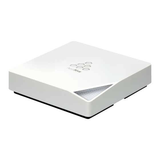
Chapter 1 The AP330 and AP350 Platforms AP330 AP350 P RODUCT VERVIEW The AP330 and AP350 models provide excellent throughput and coverage. The AP330 has internal antennas, and the AP350 has detachable external antennas. You can see the hardware components on the HiveAP in Figure 1. - Page 10 AP330 AP350 P RODUCT VERVIEW Table 1 AP330 and AP350 component descriptions (Continued) Component Description Power Connector The 12-volt DC power connector (2.0 amps) is one of two methods through which you can power the AP330 and AP350. To connect it to a 100 – 240-volt AC power source, use the AC/DC power adaptor that is available as an extra option.
-
Page 11: Ethernet And Console Ports
Chapter 1 The AP330 and AP350 Platforms Ethernet and Console Ports There are three ports on the AP330 and AP350: two RJ-45 10/100/1000Base-T/TX Ethernet ports and an RJ-45 console port. The pin assignments in the Ethernet ports follow the TIA/EIA-568-B standard (see Figure 2 on page 20). -
Page 12: Antennas
AP330 AP350 P RODUCT VERVIEW Antennas The AP330 has internal antennas, and the AP350 connects to detachable ones. Antennas for both models are described below. AP330 The AP330 has six internal single-band antennas. Three of the antennas operate in the 2.4 GHz band (IEEE 802.11b/g/n) and have a 2-5 dBi gain. -
Page 13: Mounting The Ap330 Or Ap350
Chapter 1 The AP330 and AP350 Platforms AP330 AP350 OUNTING THE Using the mounting plate and track clip, you can mount the AP330 or AP350 to the tracks of a dropped ceiling grid. Using just the mounting plate, you can mount the HiveAP to any surface that can support its weight (AP330: 1.5 lb., 0.68 kg;... -
Page 14: Surface Mount
AP330 AP350 OUNTING THE With the HiveAP upside down, align the two flexible V-shaped tabs and the security tab extension on the rail mount with the two tab slots and the security screw cavity on the underside of the HiveAP, and then push the HiveAP upward until it clicks into place as shown in Figure Figure 5 Attaching the HiveAP to the rail mount... -
Page 15: Locking The Ap330 And Ap350
Chapter 1 The AP330 and AP350 Platforms Locking the AP330 and AP350 To lock the HiveAP to the rail mount or mounting plate, use either a Kensington lock or the security screw that is included with the mounting kit. To use a Kensington lock, loop the cable attached to the lock around a secure object, insert the T-bar component of the lock into the device lock slot on the HiveAP, and then turn the key to engage the lock mechanism. -
Page 16: Device, Power, And Environmental Specifications
EVICE OWER NVIRONMENTAL PECIFICATIONS EVICE OWER NVIRONMENTAL PECIFICATIONS Understanding the range of specifications for the AP330 and AP350 is necessary for optimal deployment and device operation. The following specifications describe the physical features and hardware components, the power adapter and PoE (Power over Ethernet) electrical requirements, and the temperature and humidity ranges in which the devices can operate. - Page 17 Chapter 1 The AP330 and AP350 Platforms Aerohive...
-
Page 18: Chapter 2 The Ap340 Platform
Chapter 2 The AP340 Platform The Aerohive AP340 is a high-performance and highly reliable 802.11n wireless access point. The AP340 provides dual concurrent 802.11b/g/n and 802.11a/n radios for 3x3 MIMO (Multiple In, Multiple Out) and dual 10/100/1000 Ethernet ports for link aggregation or link redundancy. Its power management system uses a concept called smart PoE (Power over Ethernet) to adjust its power consumption automatically in response the available power in different environments. -
Page 19: Ap340 Product Overview
Chapter 2 The AP340 Platform AP340 P RODUCT VERVIEW The AP340 is a multi-channel wireless access point. It is compatible with IEEE 802.11b/g/n (2.4 GHz) and IEEE 802.11a/n (5 GHz) standards and supports a variety of Wi-Fi (wireless fidelity) security protocols, including WPA (Wi-Fi Protected Access) and WPA2. - Page 20 AP340 P RODUCT VERVIEW Table 1 AP340 component descriptions (Continued) Component Description 10/100/1000 Mbps PoE Ports The two 10/100/1000-Mbps Ethernet ports—ETH0 and ETH1—support IEEE 802.3af and 802.3at PoE (Power over Ethernet) and receive RJ-45 connectors. The HiveAP can receive power through one or both Ethernet connections from PSE (power sourcing equipment) that is compatible with the 802.3af standard and the forthcoming 802.3at standard, such as one of the PoE injectors available as an optional accessory from Aerohive.
-
Page 21: Ethernet And Console Ports
Chapter 2 The AP340 Platform Ethernet and Console Ports The AP340 has two RJ-45 10/100/1000Base-T/TX Ethernet ports and an RJ-45 console port. The pin assignments in the PoE (Power over Ethernet) Ethernet ports follow the TIA/EIA-568-B standard (see Figure 2). The ports accept standard types of Ethernet cable—cat3, cat5, cat5e, or cat6—and can receive power from power-sourcing equipment (PSE) that is 802.3af-compatible. -
Page 22: Smart Poe
AP340 P RODUCT VERVIEW Smart PoE The AP320 and AP340 apply the Aerohive concept of smart PoE to adjust power consumption as necessitated by varying levels of available power. The AP340 supports PoE on both its ETH0 or ETH1 interfaces and can draw power through either one or through both simultaneously. - Page 23 Chapter 2 The AP340 Platform Switch(config-if)#spanning-tree portfast Switch(config-if)#exit Switch(config)#interface fastEthernet 0/1 Switch(config-if)#switchport mode access Switch(config-if)#channel-group 1 mode on Switch(config-if)#spanning-tree portfast Switch(config-if)#exit Switch(config)#int fastEthernet 0/2 Switch(config-if)#switchport mode access Switch(config-if)#channel-group 1 mode on Switch(config-if)#spanning-tree portfast Switch(config-if)#exit Switch(config)#exit Switch#wr mem Finally, you must cable the Cisco switch and the HiveAP together: Cisco 0/1 to HiveAP eth0, and Cisco 0/2 to HiveAP eth1.
-
Page 24: Console Port
AP340 P RODUCT VERVIEW Console Port The pin-to-signal mapping in the RJ-45 console port is shown in Table 2 "Console port pin assignments". Table 2 Console port pin assignments HiveAP Console Port SIgnal Direction RTS (Request to Send) Output, unused RJ 45 Console port DTR (Data Terminal Ready) Output, unused 8 7 6 5 4 3 2 1... -
Page 25: Status Leds
Chapter 2 The AP340 Platform Status LEDs The five status LEDs on the top of the AP340 indicate various states of activity through their color (dark, green, amber, and red) and illumination patterns (steady glow or pulsing). The meanings of the various color + illumination patterns for each LED are explained below. -
Page 26: Configuring Antennas
AP340 P RODUCT VERVIEW Figure 4 AP340 antennas Generally, orient the antennas vertically for improved radio coverage, as shown. When mounting the AP340 on a ceiling, orient the antennas downward. 2.4 GHz Antenna for 5 GHz Antenna for IEEE 802.11b/g/n IEEE 802.11a/n Length when fully Length when fully... -
Page 27: Mimo
Chapter 2 The AP340 Platform Figure 5 Directional antenna patterns (Bird’s eye view) Patch Lower gain antennas Higher gain Higher gain Omnidirectional Antennas You typically orient omnidirectional antennas vertically, positioning them on all devices in the same direction. Omnidirectional antennas create coverage areas that can be toroidal (doughnut-shaped) or cardioid (heart- or plum-shaped), broadcasting to the sides much more effectively than up or down (see Figure 6). - Page 28 AP340 P RODUCT VERVIEW Figure 7 2x2 MIMO (2 transmit antennas x 2 receive antennas) 802.11n wireless client AP340 using two with two antennas antennas RF chains RF chains RFsignals (multipath object) Digital signal Receive Digital signal Transmit processors antennas processors antennas Reassembled...
-
Page 29: Using Mimo With Legacy Clients
Chapter 2 The AP340 Platform Figure 8 Antennas and radios 2.4 GHz (A) 5 GHz (A) Radio 1 Radio 2 RP-SMA RP-SMA 5 GHz (B) RF 802.11a/n RF 802.11b/g/n 2.4 GHz (B) connectors connectors 2.4 GHz 5 GHz 5 GHz (C) 2.4 GHz (C) Cut-away view of the AP340 to show the relationship of the antennas and the two internal radios... -
Page 30: Mounting The Ap340
AP340 OUNTING THE AP340 OUNTING THE Using the mounting plate and track clips, you can mount the AP340 to the tracks of a dropped ceiling grid. Using just the mounting plate, you can mount the HiveAP to any surface that can support its weight (3.3 lb., 1.5 kg). his document covers the following methods for mounting the AP340: •... -
Page 31: Locking The Ap340
Chapter 2 The AP340 Platform You can tie the cables to the tie points (small arched strips) on the mounting plate to prevent them from being pulled out of their connections accidentally. Figure 10 Attaching the AP340 to the mounting plate and connecting cables Mounting plate (side view) AP340 (shown as transparent for clariy) -
Page 32: Plenum Mount
AP340 OUNTING THE Plenum Mount To mount the AP340 in the plenum space above a dropped ceiling grid, you need the mounting plate, hanger clip, and a standard 24"-wide hanger frame, which can be ordered separately (SKU# AH-ACC-BKT-PLENUM). With the recessed side of the mounting plate facing downward, insert the hanger clip through the large hole in the center of the plate. - Page 33 Chapter 2 The AP340 Platform Figure 14 Clipping the hanger frame onto the track Hanger frame Remove the ceiling tile and enter the plenum. Press the hanger frame onto the ceiling track. 6. Insert the hanger clip upward through the center slot in the hanger frame, and then twist it counterclockwise until the clip snaps into a locked position against the sides of the crossbar (see Figure 15 on page 32).
-
Page 34: Suspended Mount
AP340 OUNTING THE Suspended Mount You can suspend the AP340 from a horizontal beam, post, strut, or girder. As well as the mounting plate, you ® need a quad-toggle, a 1.5 mm (0.059 inch) wire rope with hook, and a locking device. ERICO supplies these ®... - Page 35 Chapter 2 The AP340 Platform Figure 17 Suspending the AP340 Wrap the wire rope around a beam, clip the hook to the rope, and then pull the rope downward until it is taut against the beam. Push the wire rope through the side hole in the locking device and then through the Beam...
-
Page 36: Surface Mount
AP340 OUNTING THE Surface Mount You can use the mounting plate to attach the AP340 to any surface that supports its weight, and to which you can screw or nail the plate. First, mount the plate to the surface. Then, through one of the two large openings in the plate, make a hole in the wall so that you can pass the cables through to the HiveAP. -
Page 37: Device, Power, And Environmental Specifications
Chapter 2 The AP340 Platform EVICE OWER NVIRONMENTAL PECIFICATIONS Understanding the range of specifications for the AP340 is necessary for optimal deployment and device operation. The following specifications describe the physical features and hardware components, the power adapter and PoE (Power over Ethernet) electrical requirements, and the temperature and humidity ranges in which the device can operate. -
Page 38: Chapter 3 The Ap320 Platform
Chapter 3 The AP320 Platform The Aerohive AP320 Access Point is a high-performance and highly reliable 802.11n wireless access point. The AP320 provides dual concurrent 802.11b/g/n and 802.11a/n radios for 3x3 MIMO (Multiple In, Multiple Out) and dual 10/100/1000 Ethernet ports for link aggregation or link redundancy. Its power management system uses a concept called smart PoE (Power over Ethernet) to adjust its power consumption automatically in response to the available power in different environments. -
Page 39: Ap320 Product Overview
Chapter 3 The AP320 Platform AP320 P RODUCT VERVIEW The AP320 is a multi-channel wireless access point. It is compatible with IEEE 802.11b/g/n (2.4 GHz) and IEEE 802.11a/n (5 GHz) standards and supports a variety of Wi-Fi (wireless fidelity) security protocols, including WPA (Wi-Fi Protected Access) and WPA2. - Page 40 AP320 P RODUCT VERVIEW Table 1 AP320 component descriptions (Continued) Component Description ETH0 10/100/1000 Mbps PoE You can configure ETH0 and ETH1 as two individual Ethernet interfaces, Port combine them into an aggregate interface to increase throughput, or combine and ETH1 10/100/1000 Mbps them into a redundant interface to increase reliability.
-
Page 41: Ethernet And Console Ports
Chapter 3 The AP320 Platform Ethernet and Console Ports The AP320 has two RJ-45 10/100/1000Base-T/TX Ethernet ports and one RJ-45 console port. The pin assignments in the PoE (Power over Ethernet) Ethernet ports follow the TIA/EIA-568-B standard (see Figure 2 on page 20). -
Page 42: Antennas
AP320 OUNTING THE Antennas Antennas are an integral part of the AP320. The AP320 has six internal single-band antennas. Three of the antennas operate in the 2.4-GHz band (IEEE 802.11b/g/n) and have a 2-dBi gain. The other three antennas operate in the 5-GHz band (IEEE 802.11a/n) and have a 3-dBi gain. All antennas are omnidirectional, providing fairly equal coverage in all directions in a cardioid (heart-shaped) pattern around each antenna (see Figure 6 on page... -
Page 43: Ceiling Mount
Chapter 3 The AP320 Platform Ceiling Mount To mount the AP320 to a track in a dropped ceiling, you need the mounting plate, two track clips, and two Keps nuts, all of which ship as an option with the AP320. You also need a screwdriver and—most likely—a ladder. Nudge the ceiling tiles slightly away from the track to clear some space. -
Page 44: Locking The Ap320
AP320 OUNTING THE Locking the AP320 To lock the AP320 to the mounting plate, use the security screw, which is included in the mounting kit. You also need a Torx tri-wing torsion insert bit for size #1 tri-wing security screws and a screw driver that will accept the bit. - Page 45 Chapter 3 The AP320 Platform You can use the locking screw to secure the AP320 to the mounting plate. For information, see "Locking the AP320" on page If you do not pass the cables through a hole, you can run them along the wall between the wall and the mounting plate.
-
Page 46: Device, Power, And Environmental Specifications
EVICE OWER NVIRONMENTAL PECIFICATIONS EVICE OWER NVIRONMENTAL PECIFICATIONS Understanding the range of specifications for the AP320 is necessary for optimal deployment and device operation. The following specifications describe the physical features and hardware components, the power adapter and PoE (Power over Ethernet) electrical requirements, and the temperature and humidity ranges in which the device can operate. - Page 47 Chapter 3 The AP320 Platform Aerohive...
-
Page 48: Chapter 4 The Ap170 Platform
Chapter 4 The AP170 Platform The AP170 is a multi-channel mesh wireless access point with a watertight chassis that can be deployed in virtually any outdoor setting, including extreme environments. With four antennas and the ability to provide service concurrently on both 2.4 GHz and 5 GHz bands, the AP170 supports 802.11n and legacy 802.11a, b, and g clients. -
Page 49: Ap170 Product Overview
Chapter 4 The AP170 Platform AP170 P RODUCT VERVIEW The Aerohive AP170 is specifically designed for outdoor high-bandwidth wireless deployments in harsh environments. The AP170 supports a variety of authentication and security protocols, including Wi-Fi CERTIFIED™ WPA™ and WPA2™, 802.11i, WEP, 802.1X, PSK, Aerohive’s patented PPSK, and AES:CCMP, TKIP, and RC4 (WEP only) encryption. -
Page 50: Ethernet Port
AP170 P RODUCT VERVIEW Table 1 AP170 hardware components (Continued) Component Description Antenna connectors The AP170 chassis provides four antenna connectors. Two connectors on the top panel support 5 GHz antennas. Two connectors on the bottom panel support 2.4 GHz antennas. Note: You must install an antenna in every connector. 10/100/1000 The waterproof 10/100/1000 Ethernet port accepts standard Ethernet cat5, cat5e, Ethernet port... -
Page 51: Installing The Ap170
Chapter 4 The AP170 Platform AP170 NSTALLING THE This section explains how to mount a AP170 to a pole or flat surface in virtually any outdoor setting, and connect it to HiveManager over the network. Kit Contents, Required Accessories, and Tools The AP170 kit includes the items shown in Figure Figure 2 AP170 kit contents... -
Page 52: Mounting The Ap170
AP170 OUNTING THE Do not locate the AP170 enclosure near overhead power lines or other electric light or power circuits, or where it can come into contact with such circuits. During installation, exercise extreme care not to come into contact with these circuits, which can cause serious injury or death. For proper installation and grounding of the product, refer to national and local electrical codes: NFPA (National Fire Protection Association) 70, National Electrical Code Article 810 (U.S.);... -
Page 53: Vertical Pole Mount
Chapter 4 The AP170 Platform Vertical Pole Mount The following steps explain how to mount the AP170 on a vertical pole. Attach the plane bracket to the back of the unit using the hex bolts, lock washers and flat washers. Tighten the bolts with a socket or nut driver. -
Page 54: Horizontal Pole Mount
AP170 OUNTING THE Horizontal Pole Mount The following steps explain how to mount the AP170 on a horizontal pole. To mount the AP170 on a horizontal pole, first attach the plane bracket to the back of the unit using the four hex-head bolts with lock washers and flat washers. -
Page 55: Flat Surface Mount
Chapter 4 The AP170 Platform Flat Surface Mount The following steps explain how to mount the AP170 on a flat surface. You will need the plane bracket and the four sleeve-bolt assemblies. Use the plane bracket as a template to mark the location of the mounting holes on the surface. 2. -
Page 56: Attaching External Antennas
TTACHING XTERNAL NTENNAS Figure 5 Connecting the grounding cable to the grounding lug on the unit Grounding lugs Remove the short piece of cable sheath from the end of the grounding cable that does not have the connector. Wrap the exposed wires clockwise snugly around one of the six grounding lugs and tighten the nut securely. -
Page 57: Attaching The Ethernet Cable Waterproof Housing
Chapter 4 The AP170 Platform TTACHING THE THERNET ABLE ATERPROOF OUSING The following steps explain how to ensure a weatherproof seal for the Ethernet cable using the waterproof housing assembly shown in Figure Disassemble the waterproof housing. There are three pieces: a threaded nut, a slotted cable grip, and a threaded housing. 2. - Page 58 THERNET ROTECTION Figure 7 Placement of Ethernet protector in relation to the network AP170 outdoors = Ethernet cable Indoors = Wireless link Ethernet Switch Outdoor PoE To network Protector injector PoE Switch Ethernet To network Protector Ethernet Indoor PoE Protector Injector Switch Outdoor PoE...
-
Page 59: Accessing The Internal Reset Switch
Chapter 4 The AP170 Platform CCESSING THE NTERNAL ESET WITCH Although not recommended, you can remove the cover the AP170 and access an internal reset switch if necessary. The following steps describe this process. Remove the six screws that secure the top to the AP170 chassis and remove the top. Be very careful not to disturb the black rubber and woven metal gaskets when removing or replacing the device top. -
Page 60: Device, Power, And Environmental Specifications
EVICE OWER NVIRONMENTAL PECIFICATIONS EVICE OWER NVIRONMENTAL PECIFICATIONS Understanding the range of specifications for the AP170 is necessary for optimal deployment and device operation. The following specifications describe the hardware components, PoE (Power over Ethernet) electrical requirements, and the environmental ranges in which the device can operate. Device and Enclosure Specifications •... - Page 61 Chapter 4 The AP170 Platform Aerohive...
-
Page 62: Chapter 5 Ap110 And Ap120 Platforms
Chapter 5 AP110 and AP120 Platforms The Aerohive AP110 and AP120 platforms are high-performance wireless access points suitable for small offices, mobile employees, and telecommuters. The AP110 has one dual-band 802.11a/b/g/n radio, and the AP120 has two radios—one for 802.11a/n and one for 802.11b/g/n, which can both operate concurrently. Both platforms provide 2x2 MIMO (Multiple In, Multiple Out) and a single 10/100/1000 Ethernet port through which they can be powered using PoE (Power over Ethernet) that follows the IEEE 802.3af standard or the 802.3at pre-standard. -
Page 63: Ap110 And Ap120 Product Overview
Chapter 5 AP110 and AP120 Platforms AP110 AP120 P RODUCT VERVIEW The AP110 and AP120 are both multi-channel wireless access points. The AP110 contains a dual-band radio that can operate at either 2.4 GHz or 5 GHz—but not in both bands simultaneously. The AP120 contains a 2.4 GHz radio and a 5 GHz radio that can operate concurrently through four internal antennas. -
Page 64: Ethernet Port
AP110 AP120 P RODUCT VERVIEW Table 1 AP110 and AP120 component descriptions (Continued) Component Description Reset Button (Continued) To return the configuration to the factory default settings, hold it down for at least 5 seconds. After releasing the button, the status indicator goes dark as the system reboots. -
Page 65: Status Indicator
Chapter 5 AP110 and AP120 Platforms Status Indicator The status indicator has been incorporated into the Aerohive logo on the top of the AP110 and AP120. It is illuminated by various colors to indicate different states of activity. The meanings of the colors are as follows: •... -
Page 66: Mounting An Ap100 Series Device
AP100 S OUNTING AN ERIES EVICE AP100 S OUNTING AN ERIES EVICE Using one of the track clips included in the box with the HiveAP, you can mount it to a track in a dropped ceiling grid. To mount the HiveAP to any flat surface that can support its weight (1.75 lb., 0.8 kg), use two #6 or #8 screws to mount it on a wall and three screws to mount it on a ceiling. -
Page 67: Locking The Ap100 Series Device
Chapter 5 AP110 and AP120 Platforms 4. Holding the HiveAP upside down, raise it until the threaded stud on the track clip enters the hole on the HiveAP. Then revolve the HiveAP until it is firmly attached to the clip (see Figure Figure 6 Attaching the HiveAP to the track clip With the HiveAP upside down,... -
Page 68: Surface Mount
AP100 S OUNTING AN ERIES EVICE Surface Mount You can attach an AP100 series device to any flat surface that supports its weight. First, attach two screws to the surface. Then, make a hole in the wall a few inches or centimeters above the screws so that you can pass the cables through the wall to the HiveAP. -
Page 69: Device, Power, And Environmental Specifications
Chapter 5 AP110 and AP120 Platforms EVICE OWER NVIRONMENTAL PECIFICATIONS Understanding the specifications for the AP100 series platforms is necessary for optimal deployment and device operation. The following specifications describe the physical features and hardware components, the power adapter and PoE (Power over Ethernet) electrical requirements, and the temperature and humidity ranges in which the device can operate. -
Page 70: Chapter 6 The Aerohive Br100 Router
Chapter 6 The Aerohive BR100 Router Based on the Aerohive HiveOS operating system, the compact BR100 router requires virtually no intervention from the end user. The BR100 gives small offices and teleworkers full Layer 3 network capability with local DHCP and DNS services, centralized management, and firewall and VPN security. This chapter covers the following topics relating to the BR100 router: •... -
Page 71: Product Overview
Chapter 6 The Aerohive BR100 Router RODUCT VERVIEW The BR100 router is ideal for the small office or teleworkers. An IT admin at corporate headquarters either configures the CAPWAP settings manually for each device, or enables auto provisioning, which pushes the configuration to each device as soon as it establishes a connection with HiveManager. - Page 72 RODUCT VERVIEW Table 1 BR100 router component descriptions (Continued) Component Description Power connector The DC 12V/1A connector port allows you to connect the router to an appropriate power source using the AC/DC power adapter (included). Because the router does not have an on/off switch, connecting it to a power source automatically powers on the device.
-
Page 73: Radio And Antennas
Chapter 6 The Aerohive BR100 Router Radio and Antennas The BR100 contains a 1x1 single band 2.4 GHz radio that supports IEEE 802.11b/g/n and two embedded antennas with diversity. Figure 2 illustrates the radio and antennas. For a detailed description of the directional patterns for the antennas, see . -
Page 74: Mounting And Installation
OUNTING AND NSTALLATION OUNTING AND NSTALLATION You can set the BR100 router on a desktop or mount it on a wall using the wall mount keyholes on the bottom of the device. The following illustration shows these keyholes. Figure 3 Mounting the BR100 on a wall Center-to-center 1 and 7/8 inch (4.76 cm) -
Page 75: Device, Power, And Environmental Specifications
Chapter 6 The Aerohive BR100 Router EVICE OWER NVIRONMENTAL PECIFICATIONS Understanding the range of specifications for the BR100 is necessary for optimal deployment and device operation. The following specifications describe the hardware components, electrical requirements, and the environmental ranges in which the device can operate. Device and Enclosure Specifications •... -
Page 76: Chapter 7 The Hivemanager Platform
Chapter 7 The HiveManager Platform The HiveManager Network Management System provides centralized configuration, monitoring, and reporting for multiple HiveAPs. The following are a few of the many benefits that a HiveManager offers: • Simplified installations and management of up to 500 HiveAPs •... -
Page 77: Product Overview
Chapter 7 The HiveManager Platform RODUCT VERVIEW The Aerohive HiveManager is a central management system for configuring and monitoring HiveAPs. You can see its hardware components in Figure 1 and read a description of each component in Table 1 "HiveManager component descriptions". -
Page 78: Ethernet And Console Ports
RODUCT VERVIEW Table 1 HiveManager component descriptions (Continued) Component Description Serial Number Label The serial number label contains the FCC compliance stamp, model number, input power specifications, and serial number for the device. AC Power Inlet The three-prong AC power inlet is a C14 chassis plug through which you can connect a HiveManager to a 100 –... -
Page 79: Status Leds
Chapter 7 The HiveManager Platform Figure 3 Console port pin assignments RS-232 Standard Pin Assignments Pin Signal Direction Male DB-9 console port DCD (Data Carrier Detect) (unused) RXD (Received Data) Input TXD (Transmitted Data) Output DTR (Data Terminal Ready) (unused) Ground Ground DSR (Data Set Ready) -
Page 80: Rack Mounting The Hivemanager
OUNTING THE ANAGER OUNTING THE ANAGER You can mount the HiveManager in a standard 19" (48 cm) equipment rack with two rack screws—typically 3/4", 1/2", or 3/8" long with 10-32 threads. The HiveManager ships with mounting brackets already attached to its left and right sides near the front panel (see Figure 1 on page 76). -
Page 81: Device, Power, And Environmental Specifications
Chapter 7 The HiveManager Platform EVICE OWER NVIRONMENTAL PECIFICATIONS Understanding the range of specifications for the HiveManager is necessary for optimal deployment and operation of the device. The following specifications describe the physical features and hardware components, the electrical requirements for the power supply and cord, and the temperature and humidity ranges in which the device can operate. -
Page 82: Chapter 8 The High Capacity Hivemanager
Chapter 8 The High Capacity HiveManager The Aerohive High Capacity HiveManager is a management system that provides centralized configuration, monitoring, and reporting for multiple HiveAPs. The following are a few of the many benefits that a HiveManager offers: • Simplified installations and management of up to 5000 HiveAPs •... -
Page 83: Product Overview
Chapter 8 The High Capacity HiveManager RODUCT VERVIEW The High Capacity HiveManager is a central management system for configuring and monitoring HiveAPs. You can see the hardware components in Figure 1 and read a description of each component in Table 1 "High Capacity HiveManager component descriptions". - Page 84 RODUCT VERVIEW Table 1 High Capacity HiveManager component descriptions (Continued) Component Description Console Port A male DB-9 serial port to which you can make a console connection using an RS-232 (or "null modem") cable. The pin assignments are the same as those on the HiveManager and on the HiveAP (see "Ethernet and Console Ports"...
-
Page 85: Rack Mounting The High Capacity Hivemanager
Chapter 8 The High Capacity HiveManager OUNTING THE APACITY ANAGER Use the rack mounting kit to mount the High Capacity HiveManager in a standard 19" (48 cm) equipment rack. The rack mounting kit contains the following items: • (2) slide sets (each consisting of an outer slide, inner slide, and chassis rail) •... - Page 86 OUNTING THE APACITY ANAGER Figure 3 Attaching the chassis rail to the HiveManager Place the slide Chassis rail stop against the front mounting bracket. Cross-head machine screws with 10-32 threads 3. Secure the other chassis rail to the other side of the HiveManager. 4.
- Page 87 Chapter 8 The High Capacity HiveManager 7. From the front of the equipment rack, guide the chassis rails on the sides of the HiveManager into the inner slides. Then push the HiveManager into the rack until the front mounting brackets are flush against the front rack rails.
-
Page 88: Replacing Power Supplies
EPLACING OWER UPPLIES EPLACING OWER UPPLIES The high capacity HiveManager has a pair of redundant, hot-swappable power supplies. If one of the power supplies fails, the other will continue to power the device. When a a power supply fails, a continuous beeping alarm sounds and the power LED glows amber. -
Page 89: Replacing Hard Disk Drives
Chapter 8 The High Capacity HiveManager EPLACING RIVES To provide fault tolerance from disk errors and single disk failure, the high capacity HiveManager uses level 1 RAID (Redundant Array of Independent Drives) HDDs (hard disk drives). Each HDD holds identical data, the data that is written to one disk being mirrored to the other. -
Page 90: Device, Power, And Environmental Specifications
EVICE OWER NVIRONMENTAL PECIFICATIONS 12. From the list of arrays, select the one that you want to rebuild. 13. Press CTRL+R to rebuild it. The rebuild process takes about 30 minutes. When done, the utility console notifies you with a message. 14. - Page 91 Chapter 8 The High Capacity HiveManager Aerohive...
-
Page 92: Index
Index Index LED brightness control 10 locking 9, 14 aggregate interface 21 mounting, ceiling 12 antennas mounting, surface 13 configuring 25 PoE 9, 10 omnidirectional 26 power connector 9 patch 25 power specifications 15 single-direction 25 reset button 9 antennas, See also individual platform entries security screw cavity 13 AP100 series 61–68 security tab cavity 9... - Page 93 Index locking 71 rack mounting 82, 84–86 mounting and installation 73 reset button 83 power connector 71 serial number 83 power specifications 74 system fans 83 radio 72 reset button 71 USB modem connector 71 interfaces WAN port 71 aggregate 21 redundant 22 resetting the configuration 9, 19, 39, 62 LAN ports 71...
Need help?
Do you have a question about the Aerohive APs and is the answer not in the manual?
Questions and answers