
Subscribe to Our Youtube Channel
Related Manuals for Dynapac BG39 Series


Summary of Contents for Dynapac BG39 Series
- Page 1 CONCRETE EQUIPMENT CONCRETE EQUIPMENT CONCRETE EQUIPMENT CONCRETE EQUIPMENT BG39 Power Float Instructions and spare parts catalogue Manual number : 4700369451_ENG_NO.DOC Revision : 4...
-
Page 2: Table Of Contents
INSTRUCTIONS MANUAL – BG39 SUMMARY GENERAL SAFETY RULES ....................4 Machines submitted ............................4 Symbols................................4 Important rules for your safety ........................4 Safety equipment ............................4 Working area..............................4 Power supply..............................5 Starting the machine ............................5 Operation.................................5 Maintenance..............................5 Be alert ................................5 GENERAL ...........................6 DESIGN ..........................6 TECHNICAL DATA ......................6 DIMENSIONS ........................7 Working position .............................7 Transport position ............................7... - Page 3 INSTRUCTIONS MANUAL – BG39 MAINTENANCE KITS ...........................15 Dead man clutch ............................16 Centrifugal clutch ............................18 Handle BG39GS............................20 Handle BG39GF............................22 Handle BG39GS with centrifugal clutch ......................24 Handle BG39GL ............................26 Lower part BG39 (for serial numbers after february 2006) ................28 Lower part BG39 (for serial numbers before february 2006) ................30 Centrifugal clutch ............................32 File: 4700369451_ENG_NO.doc Page 3 / 36...
-
Page 4: General Safety Rules
INSTRUCTIONS MANUAL – BG39 GENERAL SAFETY RULES ACHINES SUBMITTED Powered with : Electric, Pneumatic, Petrol or Diesel engine. YMBOLS The words WARNING and CAUTION used in safety instructions, have the following meanings : WARNING indicates hazards or hazardous procedures which could result in serious injury or death , if the WARNING is not observed. -
Page 5: Power Supply
INSTRUCTIONS MANUAL – BG39 Do not use the machine in explosive environments. Do not operate a machine powered by a petrol or diesel engine in poorly ventilated spaces. These types of engines produce toxic gases which can cause serious health troubles. OWER SUPPLY WARNING Make sure that the power supply equipment complies with the relevant safety requirements of the... -
Page 6: General
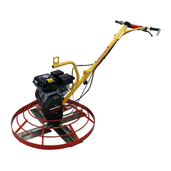
INSTRUCTIONS MANUAL – BG39 GENERAL The DYNAPAC BG39 is designed for rough and fine trowelling of concrete floors. The original manual is in English. DESIGN BG39 is driven by a four stroke petrol engine (1). They are equipped with a dead-man handle (2) which stops the rotor as soon as it is released or if the operator loose control of the operating handle (3). -
Page 7: Dimensions
INSTRUCTIONS MANUAL – BG39 BG39GF BG39GL Gasoline tank capacity l - (gal) 3.10 - (0.8) Noise level dB(A) dB(A) 7,50 3.12 Vibration exposure 1.08 0.47 Uncertainty OVERALL DIMENSIONS L x w x h (mm) 1 800 x 930 x 1 010 2530 x 930 x 1 010 (in) 70.9 x 36.6 x39.8... -
Page 8: Assembly Instructions
INSTRUCTIONS MANUAL – BG39 ASSEMBLY INSTRUCTIONS INSTALLATION OF ENGINE BG39 Available for BG39 kit (without engine) P/N 4700369605 or for engine replacement. Screw in place the four studs (1) on the base (2) (Screw driver 5 mm width). Use Loctite 243 or equivalent. -
Page 9: Installation Of Operating Handle Bg39
INSTRUCTIONS MANUAL – BG39 INSTALLATION OF OPERATING HANDLE BG39 Take off the 4 x nuts and washers from the base . Then put in place the operating handle and secure it with washers and nuts ( 17mm Flat spanner). Slide the electrical cable inside the protective tube of the operating handle and connect it to the ON/OFF switch. -
Page 10: Assembly Instructions Bg39Cc
INSTRUCTIONS MANUAL – BG39 ASSEMBLY INSTRUCTIONS BG39CC INSTALLATION OF ENGINE BG39CC Available for BG39CC Kit (without engine) P/N 4700369607 or for engine replacement . 4 washers have to be placed between the engine and the base. Put in place the engine on the plate (3) and secure it with washers (1) and screw (2) (13mm flat spanner) The clutch (4) and the key (5) (delivered with the HONDA engine) on the engine shaft . -
Page 11: Installation Of Operating Handle Bg39 Cc
INSTRUCTIONS MANUAL – BG39 - Connect the ground cable 18 to the cover holder using washer (13) and screw (14). INSTALLATION OF OPERATING HANDLE BG39 CC Take off the 4 x nuts and washers from the base . Then put in place the operating handle and secure it with washers and nuts ( 17mm Flat spanner). -
Page 12: Workshop Tools
INSTRUCTIONS MANUAL – BG39 WORKSHOP TOOLS 1x 10mm Flat spanner. 1x 13mm Flat spanner. 1x 17mm Flat spanner. 1x 5mm Hexagonal spanner . 1x 8mm Hexagonal spanner . 1x Screw driver 3 mm width. 1x Cruciform screw driver. OPERATING INSTRUCTIONS CAUTION Keep clear of rotating parts when operating. -
Page 13: Stopping
INSTRUCTIONS MANUAL – BG39 Set ON/OFF switches on "ON" position. Close choke located on the engine only if the engine is cold. After the engine starts open choke for smooth running and let the engine warm up for two or three minutes at idle speed. -
Page 14: Spare Parts Catalogue
INSTRUCTIONS MANUAL – BG39 SPARE PARTS CATALOGUE RESERVDELSTÄLLNING ORDERING SPARE PARTS Följande uppgifter ska lämmas vid beställning av To avoid errors in delivery, please give the following reservdelar för att undvika leveransfel : information when ordering spare parts : 1. Maskintyp. 1. -
Page 15: Range Of Power Floats
- The serial number of the machine - The description and the part number RANGE OF POWER FLOATS Order Type Engine brand Description numbers BG39GS HONDA 4700369257 DYNAPAC Blade arms BG39GS HONDA 4700369586 HEXAGONAL Blade arms BG39GF HONDA 4812050353 DYNAPAC Blade arms BG39GF HONDA... -
Page 16: Dead Man Clutch
4700500171 4700570004 Screw 4700503010 Screw 0147300033 Washer 4700600006 Screw 4700187171 Screw 4700533024 4700351046 Dynapac Decal 4700704500 Model Decal 4700368310 ‡ From serial number 9507007 and serial numbers 9506144 to 9506168 and 9506948 to 9506957 File: 4700369451_ENG_NO.doc Page 16 / 36... - Page 17 INSTRUCTIONS MANUAL – BG39 File: 4700369451_ENG_NO.doc Page 17 / 36...
-
Page 18: Centrifugal Clutch
INSTRUCTIONS MANUAL – BG39 ENTRIFUGAL CLUTCH BG39 All types Ref. Description Clutch cpl. 4700365639 Washer 4700603009 Spacer 4700365641 Pulley 4700363491 Spacer 4700365642 4700586018 Engine 4700182352 Cover holder 4700365643 Bearing 4700363511 Screw 4700365682 Retaining ring 4700151007 Screw 4700362216 4700570005 Washer 4700615043 V-belt 4700369259 Model decal... - Page 19 INSTRUCTIONS MANUAL – BG39 File: 4700369451_ENG_NO.doc Page 19 / 36...
-
Page 20: Handle Bg39Gs
4700185645 On/Off switch 4700364763 On/Off plate 4700365538 Membrane 4700364765 Sealing washer 4700364766 Cable 4700364119 1.7m Belly cushion 4700365495 Dynapac Decal 4700360599 Decal 4700365464 Option : Lifting eye cpl. 4700368353 Nipple * 4700368433 Holder 4700368101 Decal 4700368102 Screw 4700100145 * Kit throttle lever P/N 4700117268 File: 4700369451_ENG_NO.doc... - Page 21 INSTRUCTIONS MANUAL – BG39 File: 4700369451_ENG_NO.doc Page 21 / 36...
-
Page 22: Handle Bg39Gf
INSTRUCTIONS MANUAL – BG39 BG39GF ANDLE BG39GF P/N 4812050353 P/N 4812050354 Ref. Description Handle holder 4700363492 Cable tensionner 4700363493 Screw 4700363502 Sleeve 4700363500 Handle 4700363505 4700110682 Washer 4700600007 Screw 4700185920 Cable stop 4700363503 Belly cushion 4700365495 Screw 4700541537 Screw 4700100145 Throttle lever * 4700368434 Decal... - Page 23 INSTRUCTIONS MANUAL – BG39 File: 4700369451_ENG_NO.doc Page 23 / 36...
-
Page 24: Handle Bg39Gs With Centrifugal Clutch
Belly cushion 4700365495 4700630007 Lifting eye cpl.* 4700368353 option Washer 4700604007 Angle bar 4700367131 4700586018 Screw 4700533006 4700182119 Screw 4700367135 Dynapac decal 4700360599 Nipple * 4700368433 Decal 4700365464 Holder 4700368101 Throttle cable 4700368100 Decal 4700368102 Throttle lever * 4700368434 Screw 4700100145... - Page 25 INSTRUCTIONS MANUAL – BG39 File: 4700369451_ENG_NO.doc Page 25 / 36...
-
Page 26: Handle Bg39Gl
INSTRUCTIONS MANUAL – BG39 BG39GL ANDLE BG39GL Ref. Description Ref. Description Screw 4700100145 Shaft 4700368396 Screw 4700100146 Sleeve 4700368398 Sleeve 4700110035 Plate 4700368399 4700110682 Lifting eye 4700368400 Retaining ring 4700152014 Lower handle 4700368405 Cable stop 4700182174 Spacer 4700368406 4700183652 4700368407 Gland 4700184307 Shaft upper... - Page 27 INSTRUCTIONS MANUAL – BG39 File: 4700369451_ENG_NO.doc Page 27 / 36...
-
Page 28: Lower Part Bg39 (For Serial Numbers After February 2006)
INSTRUCTIONS MANUAL – BG39 BG39 ( 2006) OWER PART FOR SERIAL NUMBERS AFTER FEBRUARY BG39 (after February 2006) From S/N 9507007 and 9506144 to 9506168 and 9506948 to 9506957 Ref. Description Retaining ring 4700150009 4700182119 Screw 4700182122 Screw 4700182129 Bolt 4700929245 Cable stop 4700182174... - Page 29 INSTRUCTIONS MANUAL – BG39 File: 4700369451_ENG_NO.doc Page 29 / 36...
-
Page 30: Lower Part Bg39 (For Serial Numbers Before February 2006)
Screw 4700516002 Bolt 4700186265 Bolt for Robin engine 4700929245 Spacer 4700363513 Washer Screw 4700186573 4700586018 Guard ring 4700368323 Dynapac blade shaft 4700363515 Hexagonal blade shaft 4700364796 4700702681 Screw 4700500023 Dynapac blade 4700970990 Bolt-on blade 4700364814 Gear box 4700363521 Spring holder... - Page 31 INSTRUCTIONS MANUAL – BG39 File: 4700369451_ENG_NO.doc Page 31 / 36...
-
Page 32: Centrifugal Clutch
INSTRUCTIONS MANUAL – BG39 ENTRIFUGAL CLUTCH BG39 CC 4700369604 4700117236 Ref. Description Clutch pulley 4700365640 Axel 4700361909 Flange 4700361910 Spacer 4700361911 Bearing 4700361912 Retaining ring 4700150012 Retaining ring 4700361916 Screw 4700500013 Washer 4700604003 Spring 4700361913 Fly weight 4700361914 Lining 4700361915 File: 4700369451_ENG_NO.doc Page 32 / 36... - Page 33 INSTRUCTIONS MANUAL – BG39 File: 4700369451_ENG_NO.doc Page 33 / 36...
- Page 34 EO СЕРТИФИКАТ ЗА СЪОТВЕТСТВИЕ / PROHLÁŠENÍ O SHODĚ EU / EU-OVERENSSTEMMELSESRKLÆRING / CONFORMITEITSVERKLARIN EC / CERTIFICATE OF CONFORMITY EC / EUROOPA ÜHENDUSE TÜÜBIVASTAVUSE TUNNISTUS / VAATIMUSTENMUKAISUUSTODISTUS (EU) / CERTIFICAT DE CONFORMITE CE / KONFORMITÄTSBESCHEINIGUNG EG / ΠΙΣΤΟΠΟΙΗΤΙΚΟ ΣΥΜΜΟΡΦ ΣΗΣ ΕΚ / CE MEGFELELİSÉGI NYILATKOZAT / DICHIARAZIONE CE DI CONFORMITA’...
- Page 35 LIEFERANTENERKLÄRUNG Jest takŜe produkowane zgodnie wymaganiami Cumple con la NORMA EUROPEA EN12100-1, EN12100-2, EUROPEJSKICH DYREKTYW 2006/95, 2004/108, 2002/95 EN12649. oraz 2002/96, jeŜeli jest urządzenie zasilane prądem Vastab masin ka Euroopa standardile EN12100-1, EN12100- DECLARATION OF INCORPORATION EC / elektrycznym. 2, EN12649. Este de asemenea produs in conformitate cu DIRECTIVA Täyttää...
- Page 36 Atlas Copco Construction Tools AB 105 23 Stockholm Sweden We reserve the right to change specifications without notice. Photos and illustrations do not always show standard versions of machines. www.dynapac.com...
Need help?
Do you have a question about the BG39 Series and is the answer not in the manual?
Questions and answers