Advertisement
Advertisement
Table of Contents

Related Manuals for Arad Octave DN-50


Summary of Contents for Arad Octave DN-50
- Page 1 Installation Manual...
-
Page 2: Product Liability And Warranty
Such modification shall be null and void and shall not bind Arad for any and all purposes. 8. Except and to the extent provided under the warranty, in no event shall Arad be liable, whether in contract, tort or otherwise, for any damages, whether direct or indirect, consequential, incidental, special or punitive, resulting... -
Page 3: Counter Flanges
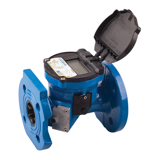
System Description and Measurement Method The OCTAVE’s measurement method is based on an ultrasonic, transit-time, dual-beam sensors which determines • the length of time it takes an ultrasonic sound wave to travel the distance between the two sensors located on the meter’s body. -
Page 4: Mechanical Data
11.0 Mechanical Data Maximum Working Pressure 16 bar Liquid Temperature 0.1 up to 50 º C Precision Class ISO 4064 rev.2014, Accuracy class 2 Configuration Compact - The display is built in to the unit Power Source 2 D size Li-battery: up to 15 years life time Environmental Protection IP 68, Ambient operation temp. - Page 5 Dimensions Dimensions Stainless Steel Meters (AWWA flanges only) Model Dctave Model Dctave Stainless Steel (mm) Threaded 50 100 150 200 250 300 Threaded Nominal size (mm) 1½ (inch) Threaded 2 Nominal size Threaded (inch) L - Length without 200 200 225 250 300 350 449 499 L - Length without couplings (mm) 254 305 356...
- Page 6 The Following Examples are Arad’s Recommendations For Achieving Top Performance When installing the Octave downstream of any hydraulic component (valve, pump) the recommended • installation requirements are no less than the drawings recommendations. For upstream & downstream straight pipes please use as much as installation site will allow (the longer the better) When installing Pressure Breaker after the meter - the pipe length should be at least 2 pipe diameter (the •...
- Page 7 13.0 Polymeric Octave Installation - General Instructions Please follow the general instructions for water meters (Check Valve, upstream & down stream and system flushing on new installations). Existing and new installations: It is recommended that the meter will NOT be installed in the middle of the system, so the meter will not suffer from the load of all the installed fixtures.
- Page 8 5. If it is not possible to use plastic connections on one side of the meter, please consider the use of our flexible couplings. These couplings were especially developed for the polymeric Octave meters. You will need to use this coupling only on one side of the meter - please install the coupling on the outlet, if possible - as described in the below pictures.
-
Page 9: Electrical Outputs
14.0 Electrical Outputs 1. Open Drain dual output 2. Dry Contact dual output 3. SSR dual output 4. Analog output (4-20mA) 5. MODBUS output 6. M - bus output 14.1. Dpen Drain dual output Connections Diagram PulseOUT#1 octave Pulse Dut Read-out PulseOUT#2 v5.2... - Page 10 14.2. Dry Contact dual output Connections Diagram Long Cable Out#1 Read-out Dctave instrument Out#2 Dry Contact 5-35 Vdc EARTH Short Cable Cables Signal connection polarity is mandatory! Wire Function Red + Drange Dut#1 Long cable Black + Brown Dut#2 5-35V+ Short cable Black 5-35V-...
- Page 11 14.3. SSR dual output Connections Diagram Long Cable Out#1 Read-out Dctave instrument Out#2 SSR v2.0 module 5-35 Vdc Short Cable Cables Signal connection polarity is mandatory! Wire Function Long cable Red + Drange Out#1 Black + Brown Out#2 5-35V + Short cable * Black 5-35V -...
- Page 12 The SSR module is powered by internal battery. External power supply in a range of 5-35Vdc could be used for certain Pulse parameters and Flow Rate combination. Pulse resolution or Pulse width are directly affect the internal battery lifetime. The following setup examples showing the calculated internal battery lifetime for 10 and 5 years: No.
- Page 13 14.4. Analog output 4-20mA • The current output is a passive 4-20mA. Power needs to be supplied by the customer. • 4mA is always “0” (zero) flow and the 20mA is programmable according to the customer requirements. (If the customer did not specify, the 20mA will be the maximum flow rate). 14.4.1.
- Page 14 14.4.2. Dutdor installation Connections Diagram Dctave Surge Read-out 4-20mA Protection instrument module 1669-03 D = 50mm Ground poll Cables *Signal connection polarity is mandatory! Wire Function current loop + Black current loop - Surge Protector In regions with potential surge and lightnings it is suggested to add Surge Protector of type - Bourns 1669-03.
- Page 15 14.5. Modbus output Connections Diagram CAT5 Modbus 2xTP Dctave Master Modbus v2.0 5-24 [Vdc] module Pulse Cables Wire Function Blue D0/A/Tx+ ModBus White/Blue D1/B/Tx- Drange 5-24Vdc White/Drange Ground Pulse Out Pulse* Black Ground * Optional Output Characteristics Dutputs Type RS485 Max Baud Rate 9600 [BPS] ax Power Consumption...
- Page 16 14.6. M-Bus output Connections Diagram M-Bus Master Dctave M-Bus V2.1 Module Pulse Cables Wire Function BUSL1 M-Bus Black BUSL2 Pulse Out Pulse* Black Ground * Optional Output characteristics Dutputs Type M-Bus Max Baud Rate 9600 [BPS] Max Power Consumption 80 [mW] M-Bus Voltage 24 - 36 [Vdc] Max Cable Length*...
- Page 17 15.0 Module Replacement / Mounting Manual 1. Properly dry the area of the connector. 2. Remove seal cover from the screw using tool with sharp edge. 3. Remove the screws using Allen key 3mm. 4. Remove the module/cover. 5. Properly dry again the area of the connector. 6.
- Page 18 Installation Manual 18 |...
- Page 19 Specifications are subject to change without notice. For the most updated version, please check our website: www.arad.co.il Installation Manual | 19...
- Page 20 Arad Ltd. Dalia 1923900, Israel, Tel: 972-4-9897911, Fax: 972-4-9897960, www.arad.co.il...
Need help?
Do you have a question about the Octave DN-50 and is the answer not in the manual?
Questions and answers
I have a flanged ARAD Flow meter IRT 80 2044536 and i am looking for installation manual as local water authority has indicated a non compliance