Table of Contents
Advertisement
Quick Links
FLUSH MOUNT (-F Model)
ConteraIP
Installation Manual
1080P
AV2756DN-F
AV2756DN-F-NL
1080P
AV2756DNIR-S
AV2756DNIR-S-NL
+1.818.937.0700
www.avcostar.com
®
MicroDome
FLUSH MOUNT (-F Model)
AV5756DN-F
SURFACE MOUNT (IR-S Model)
AV5756DNIR-S
avsales@arecontvision.com
SURFACE MOUNT (IR-S Model)
®
LX
5MP
AV5756DN-F-NL
5MP
AV5756DNIR-S-NL
Advertisement
Table of Contents

Related Manuals for AV Costar ConteraIP MicroDome LX AV2756DN-F


Summary of Contents for AV Costar ConteraIP MicroDome LX AV2756DN-F
- Page 1 FLUSH MOUNT (-F Model) SURFACE MOUNT (IR-S Model) ConteraIP ® MicroDome ® Installation Manual FLUSH MOUNT (-F Model) 1080P AV2756DN-F AV2756DN-F-NL AV5756DN-F AV5756DN-F-NL SURFACE MOUNT (IR-S Model) 1080P AV2756DNIR-S AV2756DNIR-S-NL AV5756DNIR-S AV5756DNIR-S-NL +1.818.937.0700 www.avcostar.com avsales@arecontvision.com...
-
Page 2: Table Of Contents
Page 1 of 56 Table of Contents About Our Warranty ............................2 Global (3 Year) Limited Warranty ......................2 Camera Overview ............................3 Package Contents ............................4 Installation ..............................5 In-ceiling (-F Model) Installation ........................ 5 Surface Mount (IR-S Model) ........................9 Pendant Mount (IR-S Model) ...................... -
Page 3: About Our Warranty
COSTAR™ shall have no obligation or responsibility with respect to any Product that (i) has been modified or altered without AV COSTAR’s written authorization; (ii) has not been used in accordance with applicable documentation; (iii) has been subjected to unusual stress, neglect, misuse, abuse, improper storage, testing or connection; or unauthorized repair;... -
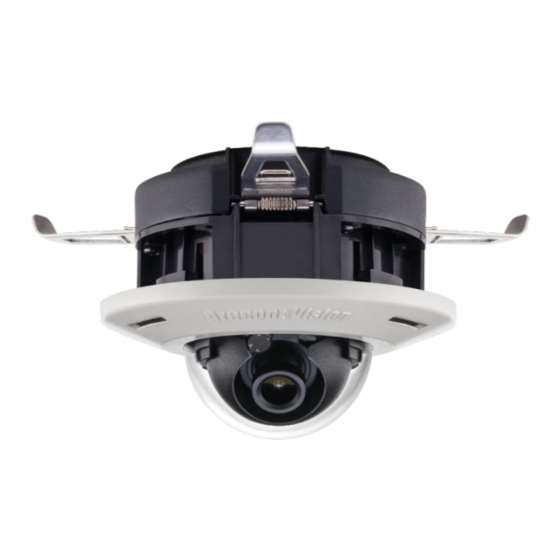
Page 4: Camera Overview
55 kg (120 lbs) of force. AV Costar™ was the first to bring H.264 to the mainstream market and recently developed SNAPstream™ (Smart Noise Adaptation and Processing) technology for reducing bandwidth without impacting image quality. -
Page 5: Package Contents
Page 4 of 56 Package Contents • AV2756DN-F / AV5756DN-F / AV2756DNIR-S / AV5756DNIR-S Description AV2756DN-F / AV5756DN-F / AV2756DNIR-S / AV5756DNIR-S IP camera Mounting Template Mounting Kit Accessory Pack... -
Page 6: Installation
Page 5 of 56 Installation In-ceiling (-F Model) Installation 1. Determine a secure location to mount the camera. Cut a hole in the ceiling using the template provided (3.25 inches in diameter) to fit the camera housing. 2. Remove the dome cover from the camera by unscrewing the captive fastener. Reference # Description Captive Fastener... - Page 7 Page 6 of 56 6. Insert the camera housing through the ceiling until the retention arms lock into place. 7. Adjust the pan and tilt to obtain the desired field of view. Then, lock the camera head in place by tightening at least two of the three set-screws with the supplied flat-head screwdriver.
- Page 8 Page 7 of 56 Reference # Description Captive Fastener 9. Tighten the captive fastener with the supplied Philips head screwdriver to secure the dome cover in place. NOTE: The supplied security torx screw may also be used.
- Page 9 Retention Arms Ceiling RJ-45 Network Connector with LED Indicators Dome Cover Captive Fastener Camera Housing 10. Use the AV Costar software AV Costar Utility located on our website ™ ™ (www.avcostar.com) for camera discovery and setup (see Instruction Manual located on...
-
Page 10: Surface Mount (Ir-S Model)
Page 9 of 56 Surface Mount (IR-S Model) 1. Determine a secure location to mount the camera. 2. Remove the dome cover from the camera by unscrewing the three captive fasteners. Figure 1: Remove dome cover 3. The camera can be mounted two ways: surface mount or via a junction box to a wall or ceiling. - Page 11 Page 10 of 56 NOTE: For installations in harsh environments, it is recommended to use all six mounting screws supplied with the camera to create the best seal possible between the camera and the mounting surface and using the supplied gasket. -or- b.
- Page 12 Page 11 of 56 5. Check that the indicator LED’s are illuminated to the desired conditions (see LED Indicator table). 6. Adjust the pan and tilt to obtain the desired field of view. Then, lock the camera head in place by tightening at least two of the three set-screws with the supplied flat-head screwdriver.
- Page 13 Page 12 of 56 Attach dome cover with captive fasteners 8. If using the MCD-4S accessory plate, tighten the two captive fasteners with the supplied Philips head screwdriver to secure the dome cover to the user supplied 4S junction box. Tightly insert the two black plugs supplied with the MCD-4S for the remaining open holes.
-
Page 14: Pendant Mount (Ir-S Model)
Page 13 of 56 Pendant Mount (IR-S Model) For a proper pendant mount installation, the MCD-CMT-W pendant mount is required (sold separately). A pendant mount should only be attached onto hard ceilings including wood, plastic, metal, and concrete. Installation Notes: 1. -
Page 15: Wall Mount (Ir-S Model)
Page 14 of 56 Wall Mount (IR-S Model) For a proper pendant mount installation, the MCD-WMT-W wall mount is required (sold separately). A wall mount should only be attached onto hard ceilings including wood, plastic, metal, and concrete. Installation Notes: 1. -
Page 16: Changing The Lens
Page 15 of 56 Changing the Lens 1. Remove the dome cover by loosening the captive fastener with the supplied Philips head screwdriver. SURFACE MOUNT (IR-S Model) FLUSH MOUNT (-F Model) 2. Manually unscrew the lens counterclockwise, this may take several seconds. 3. -
Page 17: Lens Options
Page 16 of 56 Lens Options NOTE: Spacers are required for some lens options. See table below. Lens Part Number Description Numbers of Spacers Needed MPM2.4 2.4mm MPM2.8C 2.8mm MPM4.0A MPM6.0 MPM8.0 MPM12.0A 12mm MPM16.0 16mm Removing the Bubble (-F Model) For best image quality in an indoor environment the bubble can be easily removed. -
Page 18: Camera Power Up
Page 17 of 56 Camera Power Up 1. Connect the camera to a PoE port on 100Mbps network PoE switch using an Ethernet cable. SURFACE MOUNT (IR-S Model) FLUSH MOUNT (-F Model) Connect the PoE switch to your computer’s network port by using an ethernet cable. Status Description Green... - Page 19 Page 18 of 56 Alarm I/O Functions SURFACE MOUNT (IR-S Model) FLUSH MOUNT (-F Model) Connect the Alarm In (DI) connector to the alarm input sensor, and then connect the Alarm Out (DO) connector to the alarm output signal. To avoid any damage, please follow the specification of the part as below: Alarm In (Wet Contact) Alarm Out (Wet Contact) 3.5-12 VDC...
-
Page 20: Reset To Factory Default
Page 19 of 56 Reset to Factory Default 1. Press and hold the reset button for 2 to 5 seconds, then release the reset button. This resets the camera to the factory default except for the network settings. 2. Press and hold the reset button for more than 5 seconds, then release the reset button. This resets the camera to the factory default, and this resets the network settings to the factory default. -
Page 21: Audio/Sd Card Info
Page 20 of 56 Audio/SD Card Info • SD Card Slot SURFACE MOUNT (IR-S Model) FLUSH MOUNT (-F Model) • Audio Connector SURFACE MOUNT (IR-S Model) FLUSH MOUNT (-F Model) NOTE: AV-1AK Accessory Required. Connect Y-Cable to Line In / Line Out connector. -
Page 22: Camera Discovery, Setup, And Configuration
The AV Costar™ Utility tool is efficient and convenient for mass or single camera uploads whether used for large installations that require an update to multiple settings, or smaller installations where only one camera needs to be changed. -
Page 23: Camera Discovery
Page 22 of 56 Camera Discovery 1. Locate and double click the AV Costar™ Utility shortcut on the desktop. 2. When the AV Costar™ Utility is launched, it will automatically search the ConteraIP ® cameras on the network. Also, you can manually search the camera by clicking “Discovery (Multicast)”... -
Page 24: Web Interface Navigation
Page 23 of 56 Web Interface Navigation The entire menu is located on the top of the web interface. following camera settings are available on the top of the menu in the web interface, and the user will be directed to the page that they click on the menu. Image •... - Page 25 Page 24 of 56 Focus • • Focus Range Network • Network • IP Assignment • DHCP • Port ♦ HTTP ♦ HTTPS • • IPv6 Settings • QoS (Quality of Service) • UPnP (Universal Plug and Play) • RTSP (Real Time Streaming Protocol) •...
-
Page 26: Image
Page 25 of 56 Image Menu Feature Description Brightness Controls the overall brightness of the camera image and works in conjunction with the exposure controls to maintain the image brightness. Sharpness Controls sharpness and edge definition of the image. Setting this to lower levels may make the overall image appear a bit softer while causing lines and edges in the image to look smoother. - Page 27 Page 26 of 56 Rotate Image Enable the image rotation on each channel. Mirror Image Auto Auto detects bright backlight, glare, or high contrast lighting and automatically selects the WDR level. NOTE: WDR enabled will decrease the FPS of 5MP camera. NOTE: Make sure AE mode is set to "Auto".
- Page 28 Page 27 of 56 Stream Profiles: Balanced Mode: Limits exposure time from Balance Mode 0.1ms to 66ms. The camera will keep highest -Slow Shutter FPS when Slow Shutter is unchecked. Quality Mode Quality Mode: Limits exposure time from 0.1ms to 200ms. This mode is a good compromise between reducing noise and motion blur under most lighting conditions, but with an increase in motion blur under low light...
- Page 29 Page 28 of 56 Automatic Automatic: Enables the camera to automatically switch from day mode to night mode. User can define the switching level from Day to Night or Night to Day. Day: Forces the camera to stay in day mode. Night: Forces the camera to stay in night Night mode.
- Page 30 Page 29 of 56 ROI (Regions of ROI (Regions of Interest) is used to select Interest) which areas will be monitored and recorded with higher image quality while using lower image quality for other non-ROI zones in order to save bandwidth and storage. To setup the ROI: Select the desired channel Select Main Stream or Sub Stream...
-
Page 31: Video & Audio
Page 30 of 56 Video & Audio Menu Feature Description Show Video Type: The third stream is designed for the live view on web interface, and the only option MPJEG of Video Compression is MPJEG. H.264 image quality setting for variable bit rate control. - Page 32 Page 31 of 56 Video Compression: Select the desired compression. H.265 / H.264 Resolution Select the desired resolution. Options vary based on the sensor resolution being used. Enable SNAPstream+ Enable the SNAPstream+ feature on the camera. This feature utilizes both Smart GOP and Smart ROI to reduce bitrate without impacting the image quality.
- Page 33 Page 32 of 56 Video Compression: Select the desired compression. H.265 / H.264 Resolution Select the desired resolution. Options vary based on the sensor resolution being used. Enable SNAPstream+ Enable the SNAPstream+ feature on the camera. This feature utilizes both Smart GOP and Smart ROI to reduce bitrate without impacting the image quality.
- Page 34 Page 33 of 56 Enables the Audio In / Audio Out features Audio In on the camera. Audio Out Specifies the volume level of Audio In / Audio Out: High, Middle, or Low. Volume Encoding Specifies the encoding algorithm: A-Law or U-Law.
-
Page 35: Focus
Page 34 of 56 Focus Menu Feature Description Manual Focus: Number indicates the level of focusing in order to adjust the field-of-view. +20, +5, +1, -20, -5, -1 Full-range Focus Full-range Focus button. The camera begins to autofocus with the lens stopping at the best overall point of focus. -
Page 36: Network
Page 35 of 56 Network Menu Feature Description IP Assignment: DHCP: If checked, the camera will • attempt to obtain its IP address DHCP from the DHCP server available on • IP Address the network. • Subnet Mask IP Address: Sets the current IP •... - Page 37 Page 36 of 56 IPv6 Settings: Enable IPv6: Enables IPv6 function. • Manually configures IPv6 address, Enable IPv6 Address prefix, Default route, and • IPv6 Address DNS server address. • Address Prefix Router Advertisement: Enables • Default Route Router Advertisement •...
- Page 38 Page 37 of 56 Enable RTSP Unicast Enables RTSP Unicast for stream 1 Stream (Main stream), stream 2 (Sub Stream), and stream 3 (Third Stream) Enables RTSP stream metadata for stream 1 (Main stream), stream 2 Enable RTSP Stream (Sub Stream), and stream 3 (Third metadata Stream) Configures the pathname for each...
- Page 39 Page 38 of 56 Meta IP Configures the multicast address Meta Port and the port number to the HTML meta. Path Configures the URL address of the video stream. Configures the time-to-live threshold of the multicast datagram before it is discarded by the router. Enable DDNS Enables DDNS service Host Name...
- Page 40 Page 39 of 56 No SNMP Sever Disables SNMP function SNMP v2c Enables SNMP version 2 support Community String Specifies the name of the community to access to SNMP information. Trap Configuration: Specifies the destination IP address Address to send SNMP trap messages. Community String SNMP v3 Enables SNMP version 3 support.
- Page 41 Page 40 of 56 Mode Disable: Support for HTTP only. (Optional) Support for HTTP and HTTPs both. Certificate Shows the current status of the Certificate Install New Certificate Locate Key PEM file and Key PEM file Certificate PEM file and click Certificate PEM file Upload.
- Page 42 Page 41 of 56 Protocol The default is None to disable 802.1 x functions. You can select one of the protocol options from the dropdown menu. The supported protocols are EAP-MD5, EAP-TLS, EAP-TTLS or EAP-PEAP. After the protocol has been selected, manually configure the username, password, and other required information.
-
Page 43: Privacy Mask
Page 42 of 56 Privacy Mask Menu Feature Description Enable Privacy Mask Creates a privacy mask on the image so the selected areas will not be visible. Drag mouse to: Select Mask to add privacy masks or Select Mask Unmask to remove privacy masks. Unmask... -
Page 44: Event
Page 43 of 56 Event Menu Feature Description Enable motion Turn on and off on-camera motion detection detection. Enable extended Enables the extended motion detection motion detection and motion detection zones with an increase from default 64 to 1024 for enhanced motion detection sensitivity. - Page 45 Page 44 of 56 Enable Alarm Enables Alarm Detection (Alarm In) Detection function. Alarm Schedule Configures the alarm schedule by holding down the mouse button and clicking the time block to enable the schedule settings on the selected time. A light blue color on the time block indicates that the alarm schedule is enabled, while a light grey color indicates that the alarm schedule is...
- Page 46 Page 45 of 56 Alternatively, you can manually enter the numbers to configure the hours and minutes for the “start” and “end” of the day. S: Click “S” to set up a 24-hour schedule for a particular day. D: Click “D” to clear the previous schedule for a particular day.
- Page 47 Page 46 of 56 SMTP Notification From: Specifies the email address of Handler the sender Selects a desired trigger source. The options are Trigger Alarm Detection, Trigger Motion Detection, and Trigger Tampering Alarm.
- Page 48 Page 47 of 56 SMTP Server Host Address: Specifies the host Host Address name or IP address of the SMTP server. Port Port: Specifies the port number of the SMTP server. Username Username: Specifies the login username of the SMTP server. Password Password: Specifies the login password of the SMTP server.
- Page 49 Page 48 of 56 Network Storage Enables and selects a desired trigger Handler source. The options are Trigger Alarm Detection*, Trigger Motion Detection, Trigger Tampering Alarm, and Trigger Scheduled. *This functions support depends on the model. Recipient Setup Network Storage Status: Displays the current status of the connection with Network Storage the network storage server.
- Page 50 Page 49 of 56 Mount Network Mount: Sets up a network connection Storage with the network storage server. All the video recordings or snapshots from event triggers will be uploaded to the network storage server. After the setting is complete, the Network Storage Status field will display “ok”.
- Page 51 Page 50 of 56 SD Card Information Available Storage: Displays the available storage of the SD card if it is Available Storage installed. Format SD Card: Erases all the data Format SD Card stored on the SD Card. Usage Usage: Displays the total storage that Status has been used now.
-
Page 52: System Options
Page 51 of 56 System Options Menu Feature Description Firmware Upgrade Click “Choose File” to choose the firmware upgrade file, and then click Upgrade. Download Log Records all the status information of the camera in list format. Downloads the log file to the computer as a text file. - Page 53 Page 52 of 56 Date/Time NTP Server: Synchronizes the date/time • Get Time information with defined NTP server. from After setting up the desired Time zone • NTP Server and NTP Server, click “Apply NTP • Computer Server Configuration”. System NOTE: Please make sure to set up appropriate gateway before configuring the NTP server.
-
Page 54: Administration
NOTE: If admin password was set but has been lost, it can be erased by AV Costar Utility using the key file. Please contact AV Costar™ technical support to obtain the key file required to perform this function. Or, if the camera... -
Page 55: About
Page 54 of 56 Viewer Management User List: Displays current user • User List accounts created on the camera. Clicks New User/ Delete User to create or remove a user account. User Viewer Name: Specifies the user • User Viewer name. -
Page 56: Support
Page 55 of 56 Support Menu Feature Description Support Provides several hyperlinks to get more information on the camera. - Page 57 110.00 4.33 85.00 3.35 110.00 4.33 MicroDome Flush Mount Paper Size: Letter...
- Page 58 123.00 4.84 99.00 3.90 123.00 4.84 MicroDome Surface Mount Paper Size: Letter...
- Page 59 © 2020 AV Costar™ All rights reserved. No part of this publication may be reproduced by any means without written permission from AV Costar™. The information in this publication is believed to be accurate in all respects. However, AV Costar™...
Need help?
Do you have a question about the ConteraIP MicroDome LX AV2756DN-F and is the answer not in the manual?
Questions and answers