Advertisement
Quick Links
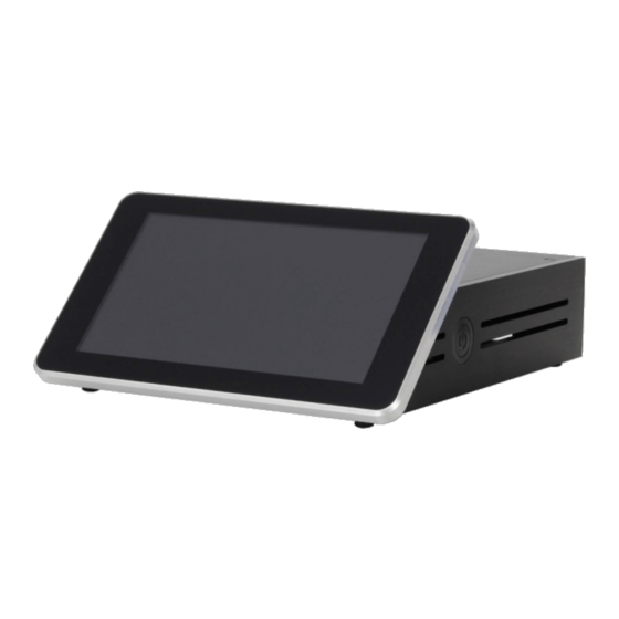
Advertisement

Related Manuals for Audiophonics RASPTOUCH RPI4


Summary of Contents for Audiophonics RASPTOUCH RPI4
- Page 1 ASSEMBLY MANUAL RASPTOUCH KIT DIY Open source network player : Raspberry Pi 3B+ & DAC...
- Page 4 RASPTOUCH First of all Thank you for choosing RaspTouch DIY Open source Network Player. Please read this manual before trying to use you RaspTouch. It will lead you through the mounting of the housing and its accessories, thus preventing any error and damage that could result from a non-adapted use.
- Page 5 RASPTOUCH Use 4 screws [V1] to install the lateral plates [F4] & [F5] on the bottom plate [F1]. Use 4 screws [V1] to install the back plate [F3] to the housing. Make it slide before fastening the screw.
- Page 6 RASPTOUCH Use 4 screws [V3] to install 4 struts [E2] to the housing next to the steep side of [F4]. Use 4 screws [V1] to mount the supports [S3] behind the display casing [F6]. Screws must be inserted from the inner side as shown on the picture.
- Page 7 RASPTOUCH Mount the PCB of your Raspberry Pi 7" display. Connect the Display Interconnect Cable (Blue marker upwards). Plug in the USB Power Cable as well. Temporarily lay the PCB against the screen casing to facilitate the process of pulling the connector through the bottom notch.
- Page 8 RASPTOUCH Clip the screen with its housing inside the main casing. Use 4 screw [V1] to mount it on the lateral plates. Use 4 bolts [F1] to fasten the screen PCB to the Struts.
- Page 9 RASPTOUCH Insert 2 screws [V4] into the holes beside the notch marked "SD" on the back plate. On the other side, slide the micro-SD extension [M1] in-between the screws and use [S2] plate to stabilize it against the casing.
- Page 10 RASPTOUCH Insert HDMI connector [M4] into the notch marked "HDMI". Mount it on the casing thanks to 2 [V5] screws and [F2] bolts.
- Page 11 RASPTOUCH Mount the on/off button [M3]. To do this, simply remove the bolt, push it through the hole from the inner side [F4] of the casing and screw the bolt back. Mount the on/off button [M3]. To do this, simply remove the bolt, push it through the hole from the inner side [F4] of the casing and screw the bolt back.
Need help?
Do you have a question about the RASPTOUCH RPI4 and is the answer not in the manual?
Questions and answers