Advertisement
Quick Links
P E N G U I N
P E N G U I N
I n s t a l l a t i o n
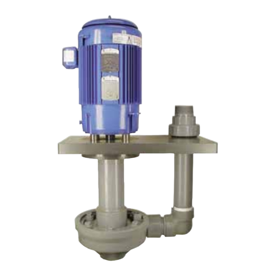
Series P-HF
HIGH FLOW VERTICAL PUMP
Penguin Pumps are designed to handle a large range of chemicals without difficulty. Completely
constructed of CPVC where in contact with the solution being pumped, Series P-HF pumps have
an upper working temperature of 180 degrees and thus can handle slurries, and most corrosive
and abrasive solutions. Series P-HF pumps are easy to install and operate, and are virtually
maintenance-free. All pumps have been tested for proper operation before leaving the factory. To
obtain optimum service life, please follow all installation and operating instructions.
Models:
P-7 1/2-HF
P-10-HF
P-15-HF
Installation & Operating Instructions
ELECTRICAL
All models are supplied with three phase dual voltage, 208-230/460V,
50/60c motors, which are not wired at the factory. When changing from
230V wiring to 460V wiring, follow the motor manufacturers wiring instruc-
tions, which can generally be found either on or in the motor junction
box. Check rotation of external fan by removing splash shield, fan spins
clockwise. It is imperative that the motor rotation be checked before op-
eration. Attach leads to motor and bump start for a maximum of a couple
of seconds as if you were turning a light switch on/off as fast as possible.
Do not leave motor running. As viewed from the suction entrance of the
pump, check for counterclockwise rotation. If clockwise rotation, change
any two hot leads and again check rotation. Replace fan splash shield.
Many options are available on the P-HF Series motors including larger
horsepowers to 15 and 575V motors. If any of these options are required,
please check the motors carefully or consult the factory.
PLUMBING
The suction side piping of the pump is extremely important. Mistakes
can usually be compensated for if made on the discharge piping.
However, piping problems on the suction side can be, and usually are,
the source of ongoing problems. If a suction line or suction extension
is required enlarge the suction line/extension by one size larger than
the suction entrance. Never reduce plumbing on the suction. Avoid
90-degree elbows and never use a 180-degree elbow. The suction
piping needs to be arranged in such a way as to allow a straight, even
flow of liquid into the eye of the impeller. This requires that all elbows,
valves, or strainers be located at a straight and uninterrupted distance
equal to at least 5-10 times the pipe diameter. Remember, elbows
create turbulence and air entrapment. Make sure every suction
coupling/connection is airtight. The bottom of the suction extension
should always be at least 2 pipe diameters above the bottom of the
tank. In either flooded suction or non-flooded suction conditions, the
use of a check valve on the discharge of the pump is recommended.
Series P-HF_D_01-15
&
M a i n t e n a n c e
Materials:
A - CPVC
PLUMBING CONTINUATION
In the case of a non-flooded suction, a flapper check valve on the end
of the submerged suction line must be installed. To facilitate priming the
pump, install a T-connection with a small valve between the pump case
and check valve. It is advisable to use a discharge valve after the check
valve. All plumbing and accessories must be supported other than by
the pump, in order to prevent possible distortion of the pump case. The
use of some hose in the discharge plumbing close to the discharge
nozzle of the pump will absorb any movement of the solid plumbing if
vibrations exists. Also a good rule of thumb is that the source solution
tank volume should be three times the flow rate of the pump.
LIQUID LEVEL
The correct liquid level is very important. A liquid level which is too high
could cause motor damage. A liquid level that is too low, below the wear
ring, may cause severe impeller damange, THIS PUMP CANNOT RUN
DRY. CHECK THE LIQUID LEVEL. The correct liquid level is halfway
between the bung hole and the centerline of the discharge nozzle.
PRIMING
Under flooded conditions, open all the valves in the suction and
discharge lines. Wait a few minutes to let entrapped air out. Throttle the
discharge valve 2/3 closed. Leave suction valves wide open. A closed
suction or discharge valve could cause damage to the impeller and the
shaft. Start the pump and open the valve to the desired flow. Under
non-flooded conditions, fill up the pump slowly from the T-connection
and valve. See recommended installation. Then throttle the discharge
valve 2/3 closed. Start the pump and continue as flooded conditions.
Model P-7 1/2-HF
Advertisement

Related Manuals for Penguin P-HF Series


Summary of Contents for Penguin P-HF Series
- Page 1 Series P-HF HIGH FLOW VERTICAL PUMP Penguin Pumps are designed to handle a large range of chemicals without difficulty. Completely constructed of CPVC where in contact with the solution being pumped, Series P-HF pumps have an upper working temperature of 180 degrees and thus can handle slurries, and most corrosive and abrasive solutions.
- Page 2 Recommended Installation Recommended High Liquid Level Low Liquid Level In Tank - Solution may pour out of weep hole during Liquid level halfway between discharge and Non-flooded conditions. Pumps will not pump operation weep hole Out of tank - Solution will pour out of weep hole and may flood motor when not in operation Suction Level Recommended...
- Page 3 P E N G U I N P E N G U I N I n s t a l l a t i o n & M a i n t e n a n c e Spare Parts List - P-7 1/2A-HF, P-10A-HF, P-15A -HF Item Description P-7 1/2A-HF P-10A-HF...
- Page 4 P E N G U I N P E N G U I N I n s t a l l a t i o n & M a i n t e n a n c e P-7 1/2A-HF thru P-15A-HF DISASSEMBLY 1.