Table of Contents
Advertisement
Quick Links
SF3500
ANALOGUE CLASS P THERMAL DETECTOR
GENERAL DESCRIPTION
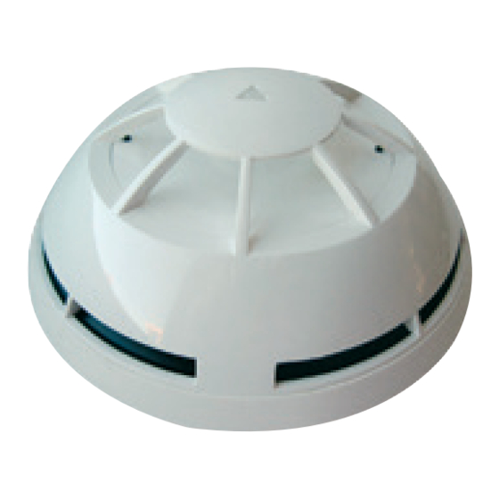
This type of detector (figure 1) continuously samples the temperature variation in the protected area to provide the earliest warning of
fire and yet offers a high level of false alarm rejection.
The digital communication protocol employed by the monitoring control panel provides high rates of information exchange in combi-
nation with comprehensive features that ensure fast and secure responses.
These detectors are designed for open area protection and must only be connected to control panels that use the proprietary ana-
logue-intelligent addressable communication protocol for monitoring and control.
The centrally positioned three-colour LED indicator (red, green and amber) provides 360° visibility and thus does not require any
orientation during installation.
An in-built magnet test allows easy activation to verify correct functioning of the detectors on site.
SHORT CIRCUIT ISOLATOR
All standard series devices are provided with short-circuit monitoring isolators on the intelligent loop's line and can be activated by
the control panel.
Note: Before installing this device please thoroughly read this leaflet and refer to the applicable European Standards and National
Codes of Practice (e.g. BS5839-1:2002 for UK) for guidance on location, spacing and acceptable use. Also seek guidance from the
compatible control panel instructions to ensure appropriate design criteria and configuration specifications are followed.
TECHNICAL SPECIFICATIONS
Power supply *
from 18 V (min) to 40 V (max)
Average standby current consumption
55 uA @ 24 V
Remote output max current consumption
20 mA
(externally limited)
Operating temperature range
-30 °C / +70 °C (no icing)
Humidity
95% RH (no condensation)
Height (standard base included)
54 mm
Diameter
110 mm
Weight (standard base included)
130 g
INSTALLATION
This heat detector must be used in combination with compatible control panels employing the communication protocol. The location
of detectors should follow recognised national or international application codes of practice.
The detector may be mounted on any of the following bases:
adaptor base / deep adaptor base
Universal adaptor base / deep adaptor base
adaptor base with shorting clip / deep adaptor base with shorting clip
Universal adaptor base with shorting clip / deep adaptor base with shorting clip
Bases supplied with a metal shorting clip installed between the two negative terminals allow more flexibility when connecting detec-
tors to the loop and permits the continuity of the loop cabling to be tested after installation and prior to the detectors being fitted.
Care must be taken to ensure that the shorting clip is either cut or removed prior to system commissioning!
Connections to the base terminals are polarity sensitive thus please check by referring to the wiring diagram in figures 2, 3,
4 and 5!
REMOTE OUTPUT CAPABILITY
Remote output capability is available as a standard feature so a remote indication lamp or a compatible platform sounder (check
power requirements) may be wired to the base terminals.
If other equipment is connected to the remote output, its supply current must be eventually limited by using an adequate
resistor. Consult the TECHNICAL SPECIFICATIONS table and assess the external device current absorption's value.
TELEDATA S.R.L. - Via Giulietti 8a, 20132, Milan, Italy
Figure 1 - View of the detector on its base.
*Product operates down to 15 V, but without LED indication.
www.Teledata-i.com
Figure 3 - Universal adaptor base and deep adaptor base loop
wiring.
Figure 5 - Universal adaptor base with shorting clip and deep
adaptor base with shorting clip loop wiring.
Figure 2 - adaptor base and deep adaptor base loop wiring.
Figure 4 - adaptor base with shorting clip and deep adaptor base
with shorting clip loop wiring.
L20-V350X-4001 (v2.3)
Advertisement
Table of Contents

Related Manuals for Teledata SF3500


Summary of Contents for Teledata SF3500
- Page 1 If other equipment is connected to the remote output, its supply current must be eventually limited by using an adequate resistor. Consult the TECHNICAL SPECIFICATIONS table and assess the external device current absorption’s value. TELEDATA S.R.L. - Via Giulietti 8a, 20132, Milan, Italy www.Teledata-i.com...
- Page 2 TDS-V350X held by the Full details on our warranty and product’s returns policy can be obtained upon request. manufacturer. TELEDATA S.R.L. - Via Giulietti 8a, 20132, Milan, Italy www.Teledata-i.com L20-V350X-4001 (v2.3)
Need help?
Do you have a question about the SF3500 and is the answer not in the manual?
Questions and answers