
Related Manuals for GCC Technologies StellarMark C Series

Summary of Contents for GCC Technologies StellarMark C Series
- Page 1 StellarMark C-Series User Manual Version 3.0 Released Feb, 2020 4F., No.236, Fude 2nd Rd., Xizhi Dist., New Taipei City 22151, Taiwan 886-2-6616-6692 Fax:886-2-2694-6875...
- Page 2 Release Note Version Release Date Change Oct, 2017 First version Modify chapter 4.2 – Pyramid Focus Tool Jan, 2019 Add chapter 4.3 – Manual Focus Tool Feb, 2020 Add CIIS series StellarMark CIIP Series User’s Manual...
-
Page 3: Table Of Contents
TABLE OF CONTENTS CHAPTER 1 SAFETY ....................1 CO2 L ..................2 RINCIPLES OF ASER ....................... 2 AFETY ATINGS ..................... 2 HE SAFETY INTERLOCK ....................2 HE SAFETY ABELS ....................9 AFETY EASURES ..................11 PERATING NVIRONMENT CHAPTER 2 UNPACKING & CONTENT ..............12 ................... - Page 4 CHAPTER 8 ERROR MESSAGE ................80 ....................81 RROR MESSAGES CHAPTER 9 EXTERNAL CONTROL ..............82 I/O P ....................83 SSIGNMENT ................85 ASER ORKING HART ................86 ASER EACTION IMING IAGRAM CHAPTER 10 BASIC MAINTENANCE ..............88 10.1 .................... 89 EGULAR SPOT CHECK 10.2 ..................
-
Page 5: Chapter 1 Safety
Chapter Safety Principles of CO Laser Safety Ratings Safety Labels The Safety Interlock System Safety Measures Operating environment StellarMark CIIS/CIIP Series User’s Manual... -
Page 6: Principles Of Co2 Laser
Principles of CO2 Laser LASER is the acronym for Light Amplification by Stimulated Emission of radiation. A CO2 laser works by electrically stimulating the molecules within a carbon dioxide gas mixture. When focused through a lens, this highly-intense, invisible beam will vaporize many materials. Depending on the speed and intensity of the projected beam, a CO2 laser may be used to mark or cut through a wide variety of materials. - Page 7 In compliance with CDRH standards, the required warning labels are affixed at the time of manufacture to the LaserPro StellarMark CIIP Series in the appropriate locations. These labels are not to be modified in any way or removed for any reason. Please familiarize yourself with the specific labels and their locations on the machine.
- Page 8 StellarMark CIIS/CIIP Series User’s Manual...
- Page 9 StellarMark CIIS/CIIP Series User’s Manual...
- Page 10 StellarMark CIIS/CIIP Series User’s Manual...
- Page 11 StellarMark CIIS/CIIP Series User’s Manual...
- Page 12 CDRH Label This label indicates the class level of CDRH. CE Label This label indicates the class level of CE Emergency Stop Label This label indicates the emergency stop button. You can find this label on the left side of the power supply unit StellarMark CIIS/CIIP Series User’s Manual...
-
Page 13: Safety Measures
Warning Label Warning Label is written all the necessary information to be aware of in every operation. Invisible laser radiation when operation. Avoid eye or skin exposure direct to laser radiation. The scan lenses are fragile. Take extra caution when installing and cleaning. Do not leave the machine unattended during operation. - Page 14 • Always wear safety goggles when the laser system is in operation. Reflective materials such as mirrors, enameled brass and anodized aluminum may partially-reflect some of the invisible laser radiation. Severe eye damage may occur if appropriate safety goggles are not worn. NOTE Each LaserPro laser machine is shipped with a single pair of safety goggles.
-
Page 15: Operating Environment
Operating Environment Please follow the guidelines when considering a suitable location to set the LaserPro StellarMark CIIP Series. Improper work environments may lead to operational malfunction and/or unsafe working conditions. The LaserPro StellarMark CIIP Series should be placed and operated in a clean environment, avoid places where the machine is exposed to high temperatures, dust, or high humidity ⚫... -
Page 16: Chapter 2 Unpacking & Content
Chapter Unpacking & Content Unpacking and Unloading Accessories Checklist StellarMark CIIS/CIIP Series User’s Manual... -
Page 17: Unpacking And Unloading
Unpacking and Unloading The StellarMark CIIP Series is shipped in one crate that contains one laser marker, one control unit, the software and all of the necessary accessories in an accessory kit. Laser Marker Accessory Kit Control unit WARNING To prevent damage to the machine or personal injury, please get assistance when loading and unloading the shipping crate. -
Page 18: Accessories Checklist
Accessories Checklist Before use, please check to see that the following items are shipped together correctly in the accessory kit. StellarMark CIIS/CIIP Series User’s Manual... - Page 19 Item Quantity Hex head screws driver LaserPro CD set (User's Manual) G-Mark Advance CD set (Software) G-Mark Advance Keypro Lens cleaner Lens cleaning paper Cotton Bud (100 units/ package) CO2#900 Goggles Lens parameter list M6 screw plastic foot Nut (M6xt5xS10). I/O Terminal Platform(5ESDVM-12P) I/O Terminal Platform(5ESDVM-10P) Laser Head Power Cable (2.5M)
-
Page 20: Chapter 3 Mechanical Overview
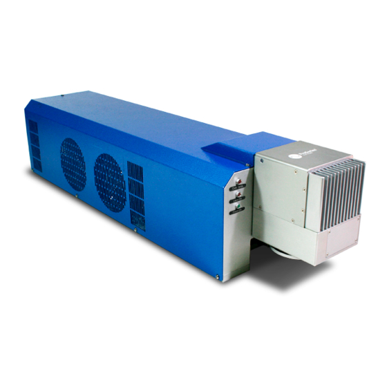
Chapter Mechanical Overview Laser Marker Control unit Foot Print StellarMark CIIS/CIIP Series User’s Manual... -
Page 21: Laser Marker
Before you complete the installation, it is a good idea to become more familiar with the machine’s features and components. You should also make note of the new features that have been developed exclusively for the StellarMark 3.1 Laser Marker Laser Tube Scan Head LED Panel... - Page 22 ⚫ Over Temp: When the red LED light is on, the laser marker will stop firing. Please turn off the master power of the laser marker and re-start it when the operating temperature is dropped below 30℃. ⚫ Laser On: When laser is firing, the red LED light is on.
- Page 23 CIIP 60Ti / 60Ti93 (5 sizes) 300DL 70x70mm 140x140mm 200x200mm 300x300mm 300x300mm ⚫ The smaller field size scan lens will produce a smaller spot size with higher marking resolution. ⚫ The larger field scan lens will produce a larger spot size with lower marking resolution.
-
Page 24: Control Unit
3.2 Control Unit Status Indicating Lights Emergency Stop ⚫ Press the button to stop the laser Laser On ⚫ in an emergency. Ready ⚫ Power on To reset this button, rotate it to the direction of an arrow. Laser Key Switch Master Power This is used to start the laser firing. - Page 25 3.2.1 Input Terminal Connector It will allow laser marker to receive signals from other automation devices. 3.2.2 Output Terminal Connector It will allow laser marker to send out the signal to the other automation devices. 3.2.3 Rotary Attachment connector It is a connector which connects to GCC provided optional item of Rotary Attachment, It allows for precise 360°...
-
Page 26: Foot Print
3.3 Foot Print CIIP 12/30 Laser Marker CIIP 60Ti / 60Ti93 Laser Marker StellarMark CIIS/CIIP Series User’s Manual... - Page 27 Control Unit StellarMark CIIS/CIIP Series User’s Manual...
-
Page 28: Chapter 4 Working Distance
Chapter Working Distance Recommended Working Distance Pyramid Focus Tool Focus Tool StellarMark CIIS/CIIP Series User’s Manual... -
Page 29: Recommended Working Distance
Recommended Working Distance Due to the characteristics of the scan lens, a certain distance between the marking object and scan lens has to be set for an optimized output quality. The working distances for different scan lens are recommended as below: Scan Lens Focus Tool Length 10x10mm... -
Page 30: Pyramid Focus Tool
Pyramid Focus Tool The innovative and patented focus tool is an accessory unit for providing the best working distance on StellarMark CIIP series. You will find the pyramid focus tool is located on bottom of the laser marker. NOTE Fixed length will be varied depend on the size of scan lens. The fixed length of Pyramid Ruler equals the recommended working distance and you will no need to adjust the length. - Page 31 NOTE 1. With this tool, you can always have the best working distance for different materials by just place your desired marking material on the z axis table and move the z axis table up until the mark material touches the bottom screw of Pyramid Ruler.
- Page 32 4.2.1 Calibrate the Pyramid Focus Tool When changing to different size scan lens for different applications, the calibration of Two Point Focus Finder position is required. Perform the adjustment per following steps. Step 1. Take out the manual focus tool from the accessories kit Step 2.
- Page 33 Step 3. Adjust the screw of the Pyramid Focus to fit the length with manual focus tool. Step 4. Calibration is completed. StellarMark CIIS/CIIP Series User’s Manual...
-
Page 34: Manual Focus Tool
4.3 Manual Focus Tool The focus tool offers you the most accurate focus distance. All you need is place the bottom of the focus tool at the position of the object to be marking and adjust the Z-axis to allow the top of the focus tool to align with the bottom of the galvo head to create the optimized focus distance. -
Page 35: Chapter 5 Machine Setup
Chapter Machine Setup Cable Connection Powering Up the Machine StellarMark CIIS/CIIP Series User’s Manual... -
Page 36: Cable Connection
Cable connection Step 1. Connect the Laser Marker Power cable between the Control unit and the Laser Marker. Step 2. Connect the USB cable between a PC or Laptop and the Control unit Step 3. Connect the SCSI cable between the Control unit and Laser Marker StellarMark CIIS/CIIP Series User’s Manual... -
Page 37: Powering Up The Machine
Step 4. Plug the software keypro to a USB connector of you PC or Laptop. Powering Up the Machine CAUTION Make sure both the LaserPro StellarMark CIIP Seres and the computer are turned off before connecting either to a power source. Step 1. - Page 38 Step 4. Turn on the master power of the Control Unit NOTE Every time you turn off the power, you are required to re-start G-Mark Advance marking software, because the connection between computer and control unit is disconnected when the power is off, so the marking software is unable to control the laser firing.
-
Page 39: Chapter 6 Software Setup
Chapter Software Setup Recommended Computer Configuration Software Installation for Windows system Software Installation for MAC system Change the Series and Model Type StellarMark CIIS/CIIP Series User’s Manual... -
Page 40: Recommended Computer Configuration
Recommended Computer Configuration The StellarMark is able to accommodate Laptop and compatible PC operating systems. Both the machine and G-Mark Basic / G-Mark Library software were designed to work best using a Windows based system with the following minimum requirements. Computer Configuration ➢... - Page 41 Step 3. Click on 32 bit or 64 bit version from the menu of the G-Mark installation CD depending on your operating system Step 4. Set the destination directory and click "Next>" StellarMark CIIS/CIIP Series User’s Manual...
- Page 42 Step 5. Select "Next>" Step 6. Installing Step 7. At 95% completion of the installation, the ModelManger window will show up StellarMark CIIS/CIIP Series User’s Manual...
- Page 43 Step 8. Select your series & model type StellarMark CIIS/CIIP Series User’s Manual...
- Page 44 Step 9. Click “OK” Step 10. Click “Finish” to complete the installation StellarMark CIIS/CIIP Series User’s Manual...
-
Page 45: Software Installation For Mac System
Software Installation for MAC system MAC users can use GCC StellarMark machines by purchasing the Parallels Desktop software which allows you to install Windows OS in MAC computers and run Windows based software under MAC computer and output with G-Mark. Step 1. - Page 46 Step 3. Read Software License Agreement and press “Accept” to continue installation Step 4. Enter your Mac OS X User Name and Password then press “OK” StellarMark CIIS/CIIP Series User’s Manual...
- Page 47 Step 5. Press “Active” Step 6. Press “OK” when activation is complete. StellarMark CIIS/CIIP Series User’s Manual...
- Page 48 Step 7. Register Parallels Desktop StellarMark CIIS/CIIP Series User’s Manual...
- Page 49 Step 8. Press “Register” and “OK” to complete the installation of Parallels Desktop. Step 9. Open Parallels Desktop (in the Applications folder) then choose File → New StellarMark CIIS/CIIP Series User’s Manual...
- Page 50 Step 10. Press “Install Windows from DVD or image file” then press “continue” to install windows OS Step 11. Select CD-ROM drive with the Windows installation CD StellarMark CIIS/CIIP Series User’s Manual...
- Page 51 Step 12. Enter the Windows OS product key Step 13. Select how you would like to run your Windows program. StellarMark CIIS/CIIP Series User’s Manual...
- Page 52 Step 14. After the prior setting is complete the windows OS installation procedure will start automatically. Step 15. Windows OS installation is complete then you can refer to “6.2 Software Installation for windows system” to install G-Mark / G-Mark Library. StellarMark CIIS/CIIP Series User’s Manual...
-
Page 53: Communication Troubleshooting
Communication Troubleshooting After installing, some computers will not install the controller driver automatically and showing an error message when you open the G-Mark software program. Please perform the following steps to solve problem. Error message 1 – Please insert KeyPro! (#1) Fix 1: Please close the G-Mark software program and re-plug the KeyPro from PC/Laptop, and then repoen the G-Mark software program. - Page 54 Step 3. Please check if there is any “!” USB device from the below chart: Step 4. Then click on “USB Driver’ and click on right mouse button and update the driver. StellarMark CIIS/CIIP Series User’s Manual...
- Page 55 Step 5. Click on ”Browse my computer for driver software” Step 6. Key in the specific path: “C:\Program Files\G-Mark Lib\Drivers\MC1. Then press “Next” StellarMark CIIS/CIIP Series User’s Manual...
- Page 56 Step 7. Press “Close” and now you can reopen the G-Mark software Error message 2 – Controller not found! Fix 1: Reconnect the USB cable between a PC or Laptop and the Control unit, and then reopen the G-Mark software program. Fix 2: Update the controller driver Step 1.
- Page 57 Step 2. Select “Device Manager” Step 3. Please check if there is any “!” USB device from the below chart: StellarMark CIIS/CIIP Series User’s Manual...
- Page 58 Step 4. Then click on “USB Driver’ and click on right mouse button and update the driver. Step 5. Click on ”Browse my computer for driver software” StellarMark CIIS/CIIP Series User’s Manual...
- Page 59 Step 6. Key in the specific path: “C:\Program Files\G-Mark Lib\Drivers\MC1. Then press “Next” Step 7. Press “Finish” and now you can activate the G-Mark software StellarMark CIIS/CIIP Series User’s Manual...
- Page 60 Fix 3: Some users of windows 10 has found the “!” USB device from list of the device manager, but cannot update the driver. We recommended you disable the driver signature enforcement on safe mode, please perform the following steps Step 1.
- Page 61 Select “Troubleshoot“. Step 5. Select “Advanced Options“ Step 6. StellarMark CIIS/CIIP Series User’s Manual...
- Page 62 Select “Startup Settings“. Step 7. Select “Restart“. Step 8. StellarMark CIIS/CIIP Series User’s Manual...
- Page 63 A menu will appear where you can press “F7” on your keyboard to Step 9. choose “Disable driver signing enforcement“. Step 10. After rebooting, go to “C:\Program Files (x86)\G-Mark Lib\Drivers\MCx” and click on “Setup.exe” to install. StellarMark CIIS/CIIP Series User’s Manual...
- Page 64 Step 11. “Windows Security” will pop up, and then click on “Install this driver software anyway” Step 12. After installing, go to device manager and make sure the controller driver has been installed. StellarMark CIIS/CIIP Series User’s Manual...
-
Page 65: Change The Series And Model Type
Change the Series and Model Type After installing G-Mark, you can change the series and model type through the model manager program. The following steps illustrate how to change the series and model type 6.4.1 Change the User Account Control Settings Step 1. - Page 66 Step 3. Set the notification to be “Never notify” and press “OK” to complete the setting 6.4.2 Setting the “Run this program as an administrator” Step 1. Find the ”G-Mark Lib” which is located at the desktop of PC StellarMark CIIS/CIIP Series User’s Manual...
- Page 67 Step 2. Position the mouse on the ”G-Mark Lib” and right-click, properties for the ”G-Mark Lib” appears then press the properties. Step 3. Click “Compatibility” tab and select checkbox “Run this program as an administrator” StellarMark CIIS/CIIP Series User’s Manual...
- Page 68 Step 4. Press “OK” to complete the setting Step 5. Find the ”ModelManager.exe” which is located at “C:\Program Files (x86)\G-Mark Lib” StellarMark CIIS/CIIP Series User’s Manual...
- Page 69 Step 6. Positions the mouse on the “ModelManager.exe” and right-click, properties for the “ModelManager.exe” appears then press the properties Step 7. Click “Compatibility” tab and select checkbox “Run this program as an administrator” StellarMark CIIS/CIIP Series User’s Manual...
- Page 70 Step 8. Press “OK” to complete the setting 6.4.3 Change the series and model type Step 1. Open the ”ModelManager.exe” which is located at “C:\Program Files (x86)\G-Mark Lib” Step 2. Model Manger window will show up, select your series & model type StellarMark CIIS/CIIP Series User’s Manual...
- Page 71 Step 3. Press “OK” to complete the change series and model type NOTE Wrong setting for series and model type may cause the machine out of order. StellarMark CIIS/CIIP Series User’s Manual...
-
Page 72: Chapter 7 Lens Adjustment
Chapter Lens Adjustment Import Lens Parameter Lens Parameter Card Lens Parameter Adjustment StellarMark CIIS/CIIP Series User’s Manual... -
Page 73: Import Lens Parameter
Import Lens Parameter Please perform the following steps: Step 1. Start the G-Mark program. Step 2. Select File→Configuration Import/Export. Step 3. Check the Application Config, Lens Setting, Object Default and Machine Check Config selections. StellarMark CIIS/CIIP Series User’s Manual... - Page 74 Step 4. Click on the Folder location icon shown below. Step 5. Locate the Lens Parameter folder in the Installation CD and select OK. (The lens parameter folder is named with the serial number of your machine.). If there is no “Lens Parameter” folder found under G-Mark installation CD, please skip to follow ”7.2 Lens Parameter Card”...
- Page 75 Step 6. Click the "Import" button. Step 7. Click on the "OK" button after the Status screen shows Complete. Step 8. Click on "OK" when the "Restart message prompts up. StellarMark CIIS/CIIP Series User’s Manual...
- Page 76 Step 9. Click on the "Work Area" Tab under the Property Table after G-Mark restarts. Step 10. The Lens parameter can be found in the Lens list. (Named with the serial number of your machine.). Step 11. Click on "Apply" after selecting the Lens and the settings will be loaded.
-
Page 77: Lens Parameter Card
Lens Parameter Card Before you start to operate the machine, the output scale of machine and the marking software must be adjusted to match each other. Or the marking lines will be distorted or will have an improper scale of the marking content. - Page 78 Step 4. Press “New” to create a new name for the lens and press “OK” Step 5. Click “Correction…” to settings lens StellarMark CIIS/CIIP Series User’s Manual...
- Page 79 Step 6. Fill in the numbers that are showing on the card to the below table. Press “Exit” to save the settings of the lens NOTE If the size of scan lens is changed, the lens parameter will be varied, too. StellarMark CIIS/CIIP Series User’s Manual...
-
Page 80: Lens Parameter Adjustment
Lens Parameter Adjustment Please perform the following steps to find the appropriate lens parameter when changing a different scan field of scan lens: Step 1. Create new name for the new lens. Step 2. Change the mark area and press “Exit” to save the settings Step 3. - Page 81 Step 4. If there is barrel square, go back to the “lens setup” to correct it. Step 5. If the figure becomes protuberant in X-axis, the X value will need to be increased like 0.002; while if now it become indentation, the X value will have to be reduced to as 0.0014.
- Page 82 Step 7. If the number is adjusted from 0.0 to 0.1, the adjustment range is from 0mm up to 0.5mm. (For 140x140mm scan lens) Keep adjusting the value until it is acceptable. Step 8. If there is an irregular parallelogram, go to the “lens parameter” under the Configure to correct the irregular angle.
- Page 83 Step 10. Measure the lengths of A, B, C, D and E of the square pattern. Make sure these lengths match to the expected length you set from the marking software. Step 11. If not, correct scale proportionally. StellarMark CIIS/CIIP Series User’s Manual...
-
Page 84: Chapter 8 Error Message
Chapter Error Message StellarMark CIIS/CIIP Series User’s Manual... -
Page 85: Error Messages
Error messages The “Alarm” error indications represent the occurrence of errors which have arisen while the system is working abnormal. When the error occurs, an “Error message” window will pop out on G-Mark software and the laser will be unable to fire until the problems are solved. Once the problem is solved, “OK”... -
Page 86: Chapter 9 External Control
Chapter External Control I/O pin assignment Laser working flow chart Laser reaction timing diagram StellarMark CIIS/CIIP Series User’s Manual... -
Page 87: I/O Pin Assignment
I/O Pin Assignment TYPE DESRIPTION There are 8 output signals (StellarMark → External O1~O8 OUTPUT device) available to communicate with external devices. ➢ Alarm OUTPUT When Alarm is inactivated, the laser marker will (Out) send signal out. ➢ When Alarm is activated, the laser marker will send out a signal out. - Page 88 ⚫ The Input and Output pins on the Control unit are corresponding with the I and O signals on the G-Mark software as below: ◆ Input pins The pin 9 ~ pin 16 from Input status are not available to Not Available communicate with laser marker.
-
Page 89: Laser Working Flow Chart
NOTE High / Low definitions in G-Mark software Laser Working Flow Chart StellarMark CIIS/CIIP Series User’s Manual... -
Page 90: Laser Reaction Timing Diagram
Definitions: Power on Time consuming between the “reading file” to the next step of “Ready to fire” will be depend on the size of working object. C~D After the file reading is completed, it will take less than < 1 µ sec for the external device to receive a “Ready”... - Page 91 ◆ Laser signal Output → External device delaying time It will take about X < 1 µ sec for the external device to receive an output signal from the laser marker → DELAY OUTPUT USER RECEIVED ◆ Laser signal Output → External device delaying time It will take about 10 µ...
-
Page 92: Chapter 10 Basic Maintenance
Chapter Basic Maintenance StellarMark CIIS/CIIP Series User’s Manual... -
Page 93: Regular Spot Check
Keeping your StellarMark CIIP Series clean and well maintained will ensure quality output, consistent reliability, and extended product life. Smoke, dust or residue build-up inside the laser system or the mechanical components can cause a reduction in the laser power, reduced product life cycle, and a host of other avoidable problems. -
Page 94: Cleaning The Scan Lens
10.2 Cleaning the scan lens Oil from hands and the residue that builds up on the focal lenses can distort the laser beam passing through, resulting in poor quality markings and may cause cracks by the uneven heat conduction. Please perform the following steps: Step 1. - Page 95 Step 3. Remove the residue mark. Step 4. Let the focal lens dry before reattaching it to the marker. Use acetone if the lens cleaner will not remove the mark. Be careful not to scratch the lens. After the mark is removed, follow the steps used to clean residue marks in order to finish the cleaning.
- Page 96 To clean the scan lens, simply remove the scan lens and inspect it for light and heavy residue marks. To clean light residue marks, apply some lens cleaner on each side of the lens. Use a new, lint free cloth to remove the lens cleaner. Make sure that the cloth only travels in one direction to prevent scratching the scan lens.
-
Page 97: Chapter 11 Appendix
Chapter Appendix StellarMark CIIS/CIIP Series User’s Manual... -
Page 98: Ciip Series Specification
11.1 CII/CIIP Series Specification Model No. CIIS 12 CIIS 30V CIIP60Ti/60Ti93 Wavelength 10.6μm 10.6μm / 9.3μm Type CO2, sealed-off Laser Source Output power Cooling Air-cooled, no water chiller required Power supply AC Auto Switching 115V / 230V, 50-60 Hz / single phase Electrical Power Requirements... - Page 99 Repeatability 0.004 mm 0.008 mm 0.012 mm 0.017 mm 0.017 mm CIIP 60Ti93 Model No. 300DL Working Area 70 x 70mm 140 x 140mm 200 x 200mm 300 x 300 300 x 300 Spot Size 0.11 mm 0.21 mm 0.32 mm 0.46 mm 0.44 mm Repeatability...
Need help?
Do you have a question about the StellarMark C Series and is the answer not in the manual?
Questions and answers