Advertisement
Quick Links
Thank you for choosing AVS. Before beginning installation, please check all parts are included and undamaged. AV
Supply Group (AVS) intends to make this manual accurate and complete. However, AVS makes no claim that the
information contained herein covers all details, conditions, or variations. Nor does it provide for every possible contin-
gency on connection with the installation or use of this product. The information contained in this document is
subject to change without notice or obligation of any kind. AVS makes no representation of warranty, expressed or
implied, regarding the information contained herein, AVS assumes no responsibility for accuracy, completeness or
su ciency of the information contained in this document.
For any parts enquiries, please contact AV Supply Group as below:
New Zealand
P 64 9 274 9172
E info@avsupply.co.nz
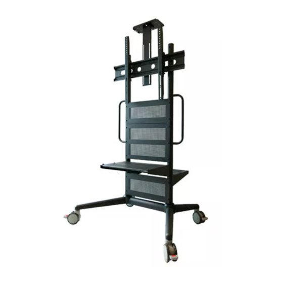
SAVC3780B
Australia
P 61 3 9071 4585
E info@avsupplygroup.com.au
Advertisement

Related Manuals for AVS SAVC3780B

Summary of Contents for AVS SAVC3780B
- Page 1 Thank you for choosing AVS. Before beginning installation, please check all parts are included and undamaged. AV Supply Group (AVS) intends to make this manual accurate and complete. However, AVS makes no claim that the information contained herein covers all details, conditions, or variations. Nor does it provide for every possible contin- gency on connection with the installation or use of this product.
- Page 2 WARNING: Exceeding the weight capacity can result in NOTE: The SAVC3780B cart can support screen sizes up to serious personal injury or damage to equipment! It is the a maximum of 80" wide. installer’s responsibility to make sure the combined weight of...
- Page 3 i l p...
- Page 4 i l p C Shelf Support (x4) D Shelf Tray (x2) A Base B Frame H Adjustable Camera G TV Mount Arm (x2) E Lockable Castor (x4) F Back Plate Support Rail I Camera Baseplate J Cable Management Clip (x3) (d) M6 x 16 Philips screw (x22) (c) M6 Washer (x6) (b) M8 Washer (x10)
- Page 5 Dimensions...
- Page 6 Install Casters to the Base Install Frame to the Base...
- Page 7 Install TV Mount to the Frame in Desired Location There are three heights you can adjust the TV via installing on di erent two sets of screw holes. Please see below: The height from the centre of the TV to the oor...
- Page 8 Install Camera Shelf in Desired Location Install Shelf Support Rail Choose which position is desired for shelves. Multiple locations are available on the front and back of TV cart. Put the shelf support into desired location. Attach the front and back trays.
- Page 9 Install TV to the TV Mounts Check the TV’s installation hole, and use the appropriate parts (f ) or (e) to install the TV to the mount arm. (f ) Flip the TV and hang it on the backplate. CAUTION: Make sure the screws are tightened once TV is in position to secure the TV.
-
Page 10: Cable Management
Cable Management... -
Page 11: Optional Accessories
Optional Accessories A. Rack Mount Kit (d) x 4 L Holder x 1 R Holder x 1 B. PC Holder (c) x 2 Wing Nut x 2 (d) x 4 PC Holder x1...
Need help?
Do you have a question about the SAVC3780B and is the answer not in the manual?
Questions and answers