Advertisement
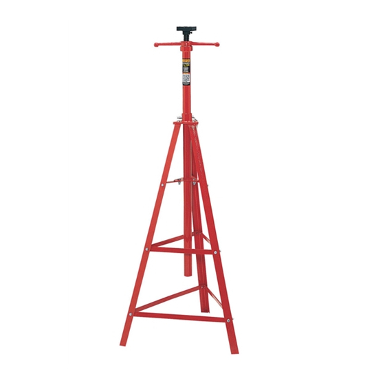
MODELS 81035 1-1/2 TON CAPACITY UNDER HOIST STAND
SETUP • OPERATING • MAINTENANCE INSTRUCTIONS
Note: Revision letters (A, B, C, D etc.) after model numbers have been omitted as they do not affect the setup,
operating and maintenance instructions of a particular jack unless otherwise noted.
IMPORTANT: READ THESE INSTRUCTIONS BEFORE OPERATING
BEFORE USING THIS DEVICE, READ THIS MANUAL COMPLETELY
AND THOROUGHLY, UNDERSTAND ITS OPERATING PROCEDURES,
SAFETY WARNINGS AND MAINTENANCE REQUIREMENTS. FAILURE
TO DO SO COULD CAUSE ACCIDENTS RESULTING IN SERIOUS OR
FATAL PERSONAL INJURY AND/OR PROPERTY DAMAGE.
The use of portable automotive lifting devices is subject to certain hazards
that cannot be prevented by mechanical means, but only by the exercise
of intelligence, care, and common sense. It is therefore essential to have
owners and personnel involved in the use and operation of equipment
who are careful, competent, trained, and qualified in the safe operation
of the equipment and its proper use. Examples of hazards are dropping,
tipping, or slipping of motor vehicles or their components caused primarily
by improperly securing loads, overloading, off-centered loads, use on other
than hard level surfaces, and using equipment for a purpose for which it
•
This stand is intended to assist in stabilizing and supporting a vehicle
that is raised by an in-ground or above-ground lift. Do not use this
under hoist stand to support a vehicle.
•
Do not exceed rated capacity.
•
Center load on saddle.
•
Do not shock load.
•
Use stands in pairs to stabilize the vehicle before starting repairs.
•
Inspect the stand(s) before each use. Do not use a stand if it is
damaged, excessively worn, altered, modified or in poor condition. Take
1.
Install the extension screw (minor diameter end first) into the
bottom of the lifting tube. Tilt the lifting tube so the extension screw
slides to the opposite end of it and comes through the bearing
housing, bearing races and bearing.
2.
Install the support saddle on the minor diameter of the
extension screw and secure it by tightening the allen socket cap
screw included with the saddle.
3.
You are now ready to assemble the stand. The whole stand
must be assembled together loosely. All bolts, lockwashers and
nuts will be tightened at the final assembly step. Install the three
long brace straps on the insides of the three angled legs so the
bottom of the stand forms a triangle. The holes in the brace straps
should line up with the holes in the legs farthest away from the
welded ends of the legs. The shortest of the three size bolts
are used for this assembly and enter into the leg holes from the
outside. The bolt then passes through a hole in a long brace strap
and is secured with the appropriate lock washer and nut.
4.
Repeat step 3 using the three shorter brace straps in the next
leg hole locations.
5.
Position the stand upright where the legs that extend from the
long brace straps are on the floor. The next series of leg holes up
from the shorter brace straps are used to attach the shortest "L"
shaped brace straps and triangular flange. Make sure you use the
triangular flange that does not include the receiver tube. Install
the longest of the smaller diameter hex bolts through the holes in
PROFESSIONAL LIFTING EQUIPMENT
was not designed.
It is the responsibility of the owner to make sure all personnel read this
manual prior to using this device. It is also the responsibility of the device
owner to keep this manual intact and in a convenient location for all to see
and read. If the manual is lost or not legible, contact Norco Industries, Inc.
for a free replacement. If the operator is not fluent in English, the product
and safety instructions shall be read to and discussed with the operator in
the operator's native language by the purchaser/ owner or his designee,
making sure that the operator comprehends its contents.
This product is covered by a Limited Lifetime Warranty. For details see the
back cover of Norco's product catalog.
WARNING
corrective action before using the stand(s).
•
Adequately support the vehicle before starting repairs.
•
Consult the lift and/or vehicle manufacturer for the proper positioning of
stands.
•
Center load on saddle. Do not use saddle's locating lugs to support the
load.
•
Be sure vehicle and stand setup are stable.
•
Use only on a hard level surface.
SETUP
the legs so the threaded ends are facing inbound. The bolt should
then pass through the hole in the short leg of the "L" shaped brace
strap and be secured with the appropriate lockwasher and nut.
Assemble all three "L" shaped brace straps the same way.
6.
Position the three "L" shaped brace straps so the long leg of
the strap faces up. Place the triangular flange on top of the three
straps where the three holes in the straps align with the three holes
in the triangular flange. Secure the flange to the brace straps using
the largest diameter hex bolts and the appropriate lockwashers
and nuts. The hex heads of the bolts should be facing up.
7.
Position the triangular flange with receiver tube on top of the
welded ends of the legs. The receiver tube should be facing up.
Align the holes in the triangular flange with the holes in the welded
ends of the legs and secure the flange to the legs using the largest
diameter hex bolts and appropriate lockwashers and nuts.
8.
Install the open end of the lifting tube through the receiver tube
in the top triangular flange and then through the hole in the lower
triangular flange.
9.
The lifting tube can be positioned at different heights in the
stand by aligning any one of its holes with the holes in the receiver
tube. The detent pin that is chained to the triangular flange with
receiver tube can be installed through the aligned holes in order to
secure the lifting tube to the stand.
10.
All bolts, lockwashers and nuts must be tightened at this time.
®
WARRANTY
Advertisement
Table of Contents

Related Manuals for Norco 81035


Summary of Contents for Norco 81035
- Page 1 FATAL PERSONAL INJURY AND/OR PROPERTY DAMAGE. and read. If the manual is lost or not legible, contact Norco Industries, Inc. for a free replacement. If the operator is not fluent in English, the product...
- Page 2 Contact Norco Industries for a replacement label if your stand’s label is The stand must be lubricated periodically in order to prevent unreadable.
Need help?
Do you have a question about the 81035 and is the answer not in the manual?
Questions and answers