Table of Contents
Advertisement
Quick Links
Advertisement
Table of Contents

Related Manuals for OmarLift HEVOS HE650

Summary of Contents for OmarLift HEVOS HE650
- Page 1 OPERATING INSTRUCTIONS FOR HEVOS HE650 VALVE D878 MGB Rev00 HE650.docx 1/50...
- Page 2 2/50 D878 MGB Rev00 HE650.docx...
-
Page 3: Table Of Contents
General Index General information ........................... 5 General Infon ............................. 6 Warning on how to operate........................ 6 Inspection on delivery ........................6 Storage .............................. 6 Disposing ............................6 Directives and technical standards considered ................. 6 Schemes and adjustments ........................7 Main components ..........................7 Hydraulic diagram .......................... - Page 4 Manoeuvres of emergency valve unit HEVOS HE650 ................30 Downward movement of the cabin ....................30 Upward movement of the cab ......................30 Parameters errors and codes HEVOS HE650 valve unit ................ 31 Parameters ............................31 Errors ............................... 36 Automatic reduction of travel times ......................39 Recovery leveling space ........................
-
Page 5: General Information
The herewith instructions aim to permit the positive and safe execution of the installation operations, starting- up, working, control, maintenance and possible repair of the unit. If any situation or event, not specified in the following pages, should occur, please refer to OMARLIFT Technical Assistance and always specifying the identification data shown on the product. -
Page 6: General Infon
1 General Infon The HE650 Valve unit is a component designed for use in lifting systems such as elevators and goods lifts. The function of the valve assembly, is to control the speed of the cabin and is to represent the stop element, downward. -
Page 7: Schemes And Adjustments
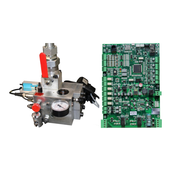
2 Schemes and adjustments Main components MAIN COMPONENTS 1 Gauge 2 Gauge cut-out cock 5 Maximum pressure valve adjusting screw - clockwise increase (+) - anticlockwise decrease (-) 12 VSC valve zero contact 16 ENR solenoid valve (unblock VNR valve) 17 Emergency manual lowering (clockwise rotation) 18 Filter 19 Ball valve... -
Page 8: Hydraulic Diagram
Hydraulic diagram LEGEND 1 Gauge 2 Gauge cut-out cock 5 Maximum pressure valve adjusting screw - clockwise increase (+) - anticlockwise decrease (-) 12 VSC valve zero contact 16 ENR solenoid valve (unblock VNR valve) 17 Emergency manual lowering (clockwise rotation) 18 Filter 19 Ball valve 20 ERS solenoid valve (unblock VSR valve) -
Page 9: Valves Functionaldiagram
Valves functional diagram LEGEND Flow meter 1 Gauge Pressure meter 2 Gauge cut-out cock Temperature meter 5 Maximum pressure valve adjusting screw VNR valve unblock solenoid valve - clockwise increase (+) - anticlockwise decrease (-) VSC valve unblock solenoid valve 12 VSC valve zero contact VSC valve command Stepper motor 16 ENR solenoid valve (unblock VNR valve) - Page 10 Measures in mm Pump connection shaft Tank unloading axis Pipe axis piston Weight: 21 kg 10/50 D878 MGB Rev00 HE650.docx...
-
Page 11: Main Components And Connections Of Sch001 Board
Main components and connections of SCH001 board ATTENTION: Reversing the polarity on the 24VDC supply, or inversion f m2 and M3 connectors, will irreparably damage the board! SUPPLY SWITCHING RELAY OUTPUT 2A-220VDC / 0.25A-250VAC M1 Input Voltage board 24-30 VDC CN9 AVV Motor Pump starting - Max input power 25 W 25 W CN10 T1 TMAX-TMIN (Par.105-110) temperature range exit:... -
Page 12: Posizioni Commutatore Rsw
Wi-fi connection (Optional) To use a Wi-Fi device for managing parameters, it is necessary to install on your Smartphone a dedicated application named Hevos OMARLIFT, which is available on Google Play Store and Apple Store. Switches the RSW selector in the position 2, the display will then indicate [UF]... -
Page 13: Sd-Card Parameters Loading
SD-CARD parameters loading To read the parameters from SD CARD must use a Micro SD 2 to 16 GB, formatted FAT 32. The card must contains the file with the number corresponding to network ID stored in the 499 parameter and PAR extension (ex. -
Page 14: Working Cycles Parameters
2.11 Working cycles parameters UPWARD PARAMETERS P201 Upward initial acceleration change rate P202 Upward accelation distance (m, ft) P203 Upward final acceleration change rate P204 Upward high speed (m/s, fpm) P205 Second upward high speed (maintenance) (m/s, fpm) P206 Third upward high speed (m/s, fpm) P207 Upward initial deceleration change rate P208 Upward deceleration distance (m, ft) P209 Second upward deceleration distance (m, ft) -
Page 15: Signal And Speed Parameters Combination
2.12 Signal and speed parameters combination Upward starting conbination 1.2.1 1.2.2.1 1.2.2.2 1.2.3 1.2.4 P453 0 or 1 0 or 1 0 or 1 0 or 1 0 or 1 0 or 1 Advance P454 Parameters. 0 or 1 0 or 1 0 or 1 0 or 1 Digital Input /... -
Page 16: Command Device Working Diagram
2.13 Command device working diagram BOARD INPUT CONNECTION SOLENOID VALVES INPUT CONNECTION SOLENOID VALVES CONNECTION V-ENR ENR INPUT CONTROL V-ERS ERS INPUT CONTROL A-ENR ENR CURRENT CONTROL A-ERS ERS CURRENT CONTROL VNR VALVE UNBLOCK SOLENOID VALVE VSC VALVE UNBLOCK SOLENOID VALVE ZERO VSC VALVE POSITION SENSOR FLOW SENSOR PRESSURE SENSOR... -
Page 17: Sch100 Board Dimensions And Fixing
2.14 SCH100 board dimensions and fixing Min. space for used N.7 Metallic spacers Board fixing Metal plate 1.5 mm for DIN 35 bracket D878 MGB Rev00 HE650.docx 17/50... -
Page 18: Upward Working Cycle
2.15 Upward working cycle UPWARD 1/8 - STATIONARY (DSP=1J1J or OFF) Ready signal RDY from board to control panel during the waiting commands UPWARD 2/8 - STARTING REQUEST (DSP=u1J) To activate Upward UP and High Speed HSP command input and make put on the solenoid valve ERS. The HSP high speed command can be replaced by MSP maintenance command (P454=0) or work together to signals MSP (P454=1), SP1 o SP2 to determine different values of high-speed set in the corresponding parameters. - Page 19 UPWARD 6/8 - DECELERATION (DSP=u3) Upon arrival at the deceleration contact in the shaft, turn off the high speed HSP signal and the valve unit executes the deceleration curve seted up in the parameters P207, P208 (209,210,218) and P211 for to obtain the low speed value corresponding to P212 parameter.
-
Page 20: Downward Working Cycle
2.16 Downward working cycle DOWNWARD 1/7 - STATIONARY (DSP=00 or OFF) Ready signal RDY from board to control panel during the waiting commands. DOWNWARD 2/7 - STARTING (DSP=d0) To activate Downward DW and High speed HSP (or SP3 if the parameter P453=1) command input and make put on the solenoid valves ENR and ERS. -
Page 21: Releveling
Subsequently the shutdown of the RDY board signal also remove the ERN and ERS solenoid inputs. The RDY board signal is active again after about 0.5 s, when the valve unit will be ready for the next travel. However do not delay to remove the ENR and ERS solenoid inputs more than 2 s from the arrival on the stopping contact in the shaft. -
Page 22: Maximum Pressure Valve Test (Dsp=Pp, Hp)
2.19 Maximum pressure valve test (DSP=PP, HP) Block the system to exclude the possibility of travel. Set the working selector RSW = 8 (DSP=PP) and then press S1 button until appear HP on display. This prepares the valve unit to execute the next upward working cycle with a progressive pressure starting and without flow error condition. -
Page 23: Upward Working Cycle Diagram
2.21 Working cycle diagram UPWARDS WORKING CYCLE DIAGRAM DOWNWARDS WORKING CYCLE DIAGRAM b Upwards deceleration contact d Upwards stopping contact f Downwards deceleration contact h Downwards stopping contact D878 MGB Rev00 HE650.docx 23/50... -
Page 24: Protection Against The Uncontrolled Movement Of The Cabin (Ucm)
The protection against uncontrolled movement must act, uphill, interrupting the electrical supply of the motor pump, while, in descent, OMARLIFT involved the use of a system formed by two electrically controlled valves and the hydraulic block (ENR solenoid valves and ERS) operating in series, that participate in the normal operation of the lift. -
Page 25: Test Device Against Uncontrolled Movement (Dsp=Uc, Up )
Test device against uncontrolled movement (DSP=uc, up ) It describes a procedure to verify the conformity of the device in accordance with section 6.3.13 of the EN81- 20 regulation. Before proceeding, verify, however, the manual of the electrical panel, the operations necessary for the tests. Usually it predisposes the implant so as to exclude the possibility of calls and open the electric chain safeties at the level of the floor doors (for the system doors must be open even if physically closed). -
Page 26: Cycle With Self Monitoring Functional Redundancy
Involved signals: Ready signal RDY from the card to the electrical panel waiting for commands. ENR activation solenoid valve VNR release ERS activation of the VSC solenoid valve release Section 3.4.1 describes the functional self-control cycle redundancy downhill Section 3.5 describes the verification of self-monitoring provided for in section 6.3.13 of the EN81-20 norm. 3.4.1 Cycle with self monitoring functional redundancy 1/4 - SIGNAL WAIT (DSP= 00) -
Page 27: Verification Of The Periodic Self-Monitoring Function Of Redundancy
The electronic board detects the necessary conditions and activates the output solenoid ERS, which controls the valve VSC. The card goes in error (error code = 19, DSP = E3) in one of the following streams situations: Incorrect coil power consumption solenoid valvole ERS Valve position VNR not on Zero Non-opening sensing valve VSC Power input ERS Solenoid valve for more than 12 s. -
Page 28: Control Of The Cycle Of Monitoring Pnp1 Signal
Control of the cycle of monitoring PNP1 signal 1/3 - SIGNALS WAITING (DSP= flfl) Ready signal RDY from the card to the waiting framework commands. 2/3 - OPERATION ACTIVATION (DSP= flfl) The signals in parentheses are used together or alternatively as in normal maneuvers. flfl 3/3 - OPERATION STOP (DSP= Verification of the supervisory function of monitoring PNP1 signal... -
Page 29: Always Check Signal Off
The serial number is the identification of the installation and component and allows the coupling to the corresponding "EU Declaration of Conformity". OMARLIFT keeps a database in the list of Customer, Customer Order Reference, number of component series which allows traceability with historical sampling archives and manufacture of components. -
Page 30: Manoeuvres Of Emergency Valve Unit Hevos He650
4 Manoeuvres of emergency valve unit HEVOS HE650 Downward movement of the cabin The automatic emergency, in the case of mains failure, must use devices of the valves of the group , that working during the normal descent maneuver, powered by a battery 24 VDC and 100 W. For the manually downhill maneuver operate the knob 17, in a clockwise direction, up to a level where the passengers can get out of the cab. -
Page 31: Parameters Errors And Codes Hevos He650 Valve Unit
5 Parameters errors and codes HEVOS HE650 valve unit Parameters The parameters of the series P1, P2, P3, P5 and P6 have free access, while those of series P4, P7 and P8 need the setting of parameter P199 with the value = 8369111 (user password), which will reset when you disconnect the device or you re-enter in P199 parameter. - Page 32 Upward travel: with VVVF driver = 1, 231 Y/N VVVF with microlevelling = 2, hybrid with VVVF=3 Soft stop setting, if = 1 upward travel with 232 Y/N SoftS U soft stop 233 OverSpeed U Nominal speed maximum increasing Parameter Default Large Description Unit...
- Page 33 STEPPER upward start time delay from 424 Pause ERS U 425 Pos Min MPP STEPPER position inferior limit step 23000 2000 <= P402 STEPPER downward start time delay from 426 Pause ERS D 427 TemperZeroM Flow meter zero temperature °C 430 Start Time1 STEPPER starting time 1 s/1000...
- Page 34 492 Offset Mis1 Flow meter zero position 1 10000 493 Offset MsT2 Flow meter zero temperature 2 °C 494 Offset Mis2 Flow meter zero position 2 10000 497 A3 Error A3 monitoring during error: 1=Activate, 2=Also maximum time 499 Network ID Network ID 99999999 12345678 Parameter...
- Page 35 569 Mach Time Machine time step 20000 571 VNR closed VNR valve closed step 20000 572 Active Node Multi-Valve system attive CAN nodes 3355443 580 A3 TimeTest Time between A3 tests 596 Vers Boot Bootloader version 597 SoftW Vers Software version 3355443 598 Board SN Board SN...
-
Page 36: Errors
872 Gain U0-1 UPward gain U0-1 5000 1000 881 Integrat U Upward integrative factor 1000 882 Integrat D Downward integrative factor 1000 883 IntegStop D Downward stopping integrative factor 1000 887 Flux Cor U Up flow valve mapping correction % +/- 2000 888 Flux Cor D Down flow valve mapping correction... - Page 37 ERROR description Cause / Corrective Action Maneuver blocked with a specific error that follows Analyze the number of next error (Er) (Er) Auxiliary power absence Check board voltage supply (EA) High temperature limit TMAX Check the P105 parameter value and the fluid working temperature (EA) Low temperature limit TMIN Check the P110 parameter value and the fluid working...
- Page 38 (EA) WiFi error WiFi module is not installed or defective (Er) Stepper driver undervoltage Check voltage supply board (Er) Stepper driver overcurrent Check voltage supply board (Er) MPP starting anomaly MPP or ERS valve or 12 zero sensor problem Not used (Er) Stepper step loss MPP driver signaling valve ERS electro \ mechanical problem...
-
Page 39: Automatic Reduction Of Travel Times
Reduce travel times it allows to increase performance of 'elevator and upward, in the presence of a constant speed motor-pump, reduce consumption and oil heating. In the valve group Hevos HE650 the reduction of travel times is realized in two modes: automatic reduction of upward and downward leveling space, expressed as the traveled at low speed before stopping. -
Page 40: With Vvvf Drive Working Valve Unit Hevos He650
2 x 0.02 [m] / 0.05 [m/s] = 0.8 s With VVVF drive working valve unit HEVOS HE650 The valve unit Hevos 650 can work in conjunction with a VVVF drive, dedicated for the hydraulics systems, which works upward for adjust the speed of equipment, by setting the parameter P231 = 1. -
Page 41: Maintenance Valve Unit Hevos He650
7 Maintenance valve unit HEVOS HE650 Maintenance program and periodic checks Recommended time List control operations Installat. Month Annual 10 years SCH001 BOARD ERROR STORAGE GROUP AND GAUGE SHUT-OFF VALVE VALVES LEAKAGES EXTERNAL LEAKAGES WORKING PRESSURES PRESSURE RELIEF VALVE CALIBRATION... -
Page 42: Filters And Solenoid Valve
FLRS - Solenoid valve filter ERS - code DSG09903201 The valve group HEVOS HE650 can work setting P231 = 2 parameter in combination with an auxiliary micro- levling group that works in upward travel to recover the right flor level to without the mail motor. - Page 43 Note: the stopping distance depends exclusively on the speed of the car during the ascent movement and is normally different from that performed in a normal run under group control. It is recommended the use of specific stop contacts when micro-leveling stopping. To connect the auxiliary group contact the Technical Office.
-
Page 44: Schemes And Adjustments Multi-Valve
P102 defines the rated flow of the pump of the individual Hevos HE650. A series of specific parameters allow the configuration of the multi-valve system:... -
Page 45: Hydraulic Scheme
Hydraulic scheme D878 MGB Rev00 HE650.docx 45/50... -
Page 46: Connections Master - Slave
Connections master - slave MAIN CARD SCHEDA PRINCIPALE (MASTER) (MASTER) sockets interchangeable CAN The jumper JP5 is to be inserted in both terminator cards, while it is to be let free those intermediatedie The connections to the devices valve groups and the power of the board are the same as those of the single group... -
Page 47: Diagram Of Functioning Control Devices
Diagram of functioning control devices MAIN CARD (MASTER) DOWNWARD EN81-20 TRAVEL EN81- ELECTRIC PANEL SECONDARYCARD (SLAVE) DOWNWARD EN81-20 TRAVEL EN81-20 BOARD INPUT CONNECTION VALVE COMAMND STEPPER SOLENOID VALVES INPUT MOTOR CONNECTION D-MPP STEPPER MOTOR CONTROL DRIVER SOLENOID VALVES CONENCTION STEPPER MOTOR CONNECTION RELAY... -
Page 48: Eu-Type Certificate (Example)
9 EU-type certificate (example) 48/50 D878 MGB Rev00 HE650.docx... - Page 49 D878 MGB Rev00 HE650.docx 49/50...
- Page 50 OMARLIFT s.r.l. Via F.lli Kennedy, 22/D 24060 Bagnatica (BG) – ITALY Phone +39 035 689611 Fax +39 035 689671 Email: info@omarlift.eu Web: http://www.omarlift.eu 50/50 D878 MGB Rev00 HE650.docx...
Need help?
Do you have a question about the HEVOS HE650 and is the answer not in the manual?
Questions and answers