Advertisement
Quick Links
Keithley Instruments
28775 Aurora Road
Cleveland, Ohio 44139
1-800-833-9200
tek.com/keithley
Overview
The Keithley Instruments Model 4225-RPM and 4225-RPM-LR Remote Preamplifier/Switch Modules are
remote amplifiers and automatic switches.
The 4225-RPM is a multiplexer switch that automatically switches between precision dc source-measure units
(SMUs), C-V, and the ultra-fast pulsed I-V instruments. In addition, the Remot Preamplifier/Module (RPM)
extends the low current measurement capability of the 4225-PMU Ultra-Fast Pulsed I-V Instrument Module.
The Model 4225-RPM-LR is a lower output resistance version of the 4225-RPM. This lower output resistance
allows for a more accurate RPM voltage output at higher currents than the 4225-RPM. Performance tradeoffs
may result, especially when making measurements of high capacitive loads.
PA-1086 Rev. A October 2020
Model 4225-RPM and Model 4225-RPM-LR
Remote Pulse Module Instructions
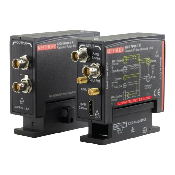
Figure 1: 4225-RPM and 4225-RPM-LR
*PPA-1086A*
1
Advertisement

Related Manuals for Keithley 4225-RPM


Summary of Contents for Keithley 4225-RPM
- Page 1 4225-PMU Ultra-Fast Pulsed I-V Instrument Module. The Model 4225-RPM-LR is a lower output resistance version of the 4225-RPM. This lower output resistance allows for a more accurate RPM voltage output at higher currents than the 4225-RPM. Performance tradeoffs may result, especially when making measurements of high capacitive loads.
-
Page 2: Included Accessories
Model 4225-RPM and Model 4225-RPM-LR Remote Pulse Module Instructions Included accessories The following cables, adapters, and accessories are included in the remote pulse module kit. Figure 2: 4225-RPM and 4225-RPM-LR accessories Item Description Keithley part number Quantity RPM interconnect cable, 2.4 m (8 ft) CA-547-2.4... -
Page 3: Related Documents
Model 4225-RPM and Model 4225-RPM-LR Remote Pulse Module Instructions Indicators When the RPM is operational in a 4200A-SCS system, an LED on top of the RPM illuminates. The color of the LED indicates which instrument is connected to the DUT during a test. Use the color codes in the following figure to determine which instrument is connected. - Page 4 To prevent possible settling and impedance matching problems that may affect proper ranging and LLEC operation, do not mix 4225-RPMs and 4225-RPM-LRs in one system. Use either all 4225-RPMS or all 4425-RPM-LRs. Connections from the 4225-PMU to an RPM The following figure shows the connection from the 4225-PMU to either RPM.
- Page 5 Model 4225-RPM and Model 4225-RPM-LR Remote Pulse Module Instructions Connections to a 4-terminal device The following illustrates the connection to a 4-terminal device using the cabling and adapters that are included with either RPM or the 4225-PMU. Figure 5: RPM output connection to 4-terminal device...
- Page 6 Model 4225-RPM and Model 4225-RPM-LR Remote Pulse Module Instructions Typical 2-terminal connections The following figure illustrates the connections to 2-terminal devices using the optional MMPC cabling. This figure shows two 4225-RPMs or 4225-RPM-LRs and two 4210-MMPC cable kits. Figure 6: Typical diode connections PA-1086 Rev. A October 2020...
- Page 7 Figure 7: Typical MOSFET connection RPM lower current ranges The 4225-RPM or 4225-RPM-LR extends the lower current ranges of the 225-PMU. This is especially important for devices like diodes or transistors that have I-V curves that extend over several decades of current. The autorange feature of the 4225-RPM and 4225-RPM-LR enables automatic range selection while a pulsed I-V sweep is in progress.
- Page 8 The main difference between the 4225-RPM and the 4225-RPM-LR is output resistance. The 4225-RPM has between 20 Ω and 50 Ω of output resistance. The 4225-RPM-LR has 2 Ω to 3 Ω of output resistance. This low output resistance is important for customers who need more accurate low voltage output at currents up to 10 mA without using the Load Line Effect Compensation (LLEC) feature to improve this low voltage accuracy at higher currents.
- Page 9 Model 4225-RPM and Model 4225-RPM-LR Remote Pulse Module Instructions Figure 8: VDS-IDS curves for a MOSFET showing the load-line effect at high currents The 4225-RPM has resistance in series with its output (typically between 20 Ω and 50 Ω). It also exhibits the load-line effect.
- Page 10 4225-PMU, which has 50 Ω of output resistance. When a test requires more than 10 mA of current, the output resistance changes from the 4225-RPM-LR output resistance (2 Ω to 3 Ω) to the PMU output resistance (50 Ω). Current measurements outside the RPM range show the typical 50 Ω...
-
Page 11: Safety Precautions
Keithley products are designed for use with electrical signals that are measurement, control, and data I/O connections, with low transient overvoltages, and must not be directly connected to mains voltage or to voltage sources with high transient overvoltages. - Page 12 (note that selected parts should be purchased only through Keithley to maintain accuracy and functionality of the product). If you are unsure about the applicability of a replacement component, call a Keithley office for information.
Need help?
Do you have a question about the 4225-RPM and is the answer not in the manual?
Questions and answers