
Related Manuals for MicaSense DLS 2


Summary of Contents for MicaSense DLS 2
- Page 1 DLS 2 Integration Guide Rev 03 Downwelling Light Sensor 2 (DLS 2) Integration Guide Revision 03, Jan 2020 Seattle, WA © 2020 MicaSense, Inc. Page 1 of 17 ...
-
Page 2: Table Of Contents
Magnetic Heading Check 1 1 Magnetic Interference Check 1 3 Basic Integrations 1 4 Standalone Integration Using RedEdge-MX and DLS 2 14 Example RedEdge-MX + DLS 2 Integration 15 Standalone Integration Using Altum and DLS 2 1 6 ... -
Page 3: Overview And Scope
MicaSense sensor (RedEdge 3, RedEdge-M, RedEdge-MX, and Altum). During a mission, the DLS 2 measures the ambient light and sun angle for each of the five bands of the camera and records this information in the metadata of the TIFF images ... -
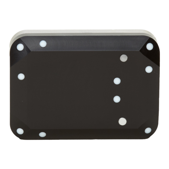
Page 4: Measurements And Attachment Points
DLS 2 Integration Guide Rev 03 Measurements and Attachment Points BOTTOM Height 14.03 mm Width 46.00 mm Length 63.50 mm Weight 49 g © 2020 MicaSense, Inc. Page 4 of 17 ... -
Page 5: Dls 2 Connectors And Buttons
SIDE DLS 2 Connectors and Buttons The sensor kit includes all required interface cables to connect to the DLS 2. The LED camera status indicator mimics the LED signals on the MicaSense sensor. The signal types are outlined in the Sensor Firmware Guide. The camera trigger button will command a ... -
Page 6: Dls 2 Installation Guidelines
DLS 2 Installation Guidelines The DLS 2 should always be the highest object on the aircraft in order to avoid shadows or reflections. It contains an integral GPS sensor that may be utilized for geotagging of the MicaSense sensor imagery if system GPS signals are not provided to the sensor by other ... -
Page 7: Fixed-Wing
DLS 2 light sensor as this may interfere with incoming light values. Multirotor Install the DLS 2 on a rigid post such that it is the highest object on the aircraft, with a minimum of 5 cm above the rotor plane. ... - Page 8 DLS 2 module. Ensure that the DLS 2 is connected to the Sensor using the provided cables. Additionally, your DLS 2 module should be rigidly mounted to your aircraft frame. ...
- Page 9 DLS 2 Integration Guide Rev 03 NOTE Before beginning the calibration routine, position yourself and the drone away from large metal objects such as cars and buildings. Also avoid paved areas, which may have metal rods inside the cement. An open field is preferred to avoid ...
- Page 10 The drone and DLS 2 module should also be kept level to the plane they are on in each position. The on-screen rotation guide will show you when you have successfully ...
-
Page 11: Magnetic Heading Check
DLS 2 Integration Guide Rev 03 NOTE If you are using a Serial or HTTP connection to supply GPS and attitude information to the sensor, you do not need to perform the magnetometer calibration described above. ... - Page 12 DLS 2 Integration Guide Rev 03 Additionally, you will want to perform a magnetic interference test to verify that your drone will not affect the heading readings during flight. © 2020 MicaSense, Inc. Page 12 of 17 ...
-
Page 13: Magnetic Interference Check
Electromagnetic interference during the operation of your drone can cause errors in the magnetic heading readings. This can cause the irradiance data generated by the DLS 2 to be not usable during processing. © 2020 MicaSense, Inc. Page 13 of 17 ... -
Page 14: Basic Integrations
Rev 03 Basic Integrations MicaSense sensors are designed for integration into a variety of platforms. Below are some common integration configurations. 1. Standalone Integration Using RedEdge-MX and DLS 2 The standalone integration option requires only that power is provided to the RedEdge-MX ... -
Page 15: Example Rededge-Mx + Dls 2 Integration
DLS 2 Integration Guide Rev 03 Example RedEdge-MX + DLS 2 Integration © 2020 MicaSense, Inc. Page 15 of 17 ... -
Page 16: Standalone Integration Using Altum And Dls
The standalone integration option requires only that power is provided to the Altum system. Triggering is configured via the WiFi interface to either “Overlap” or “Timer” mode. GPS information is provided by the integrated GPS receiver within the DLS 2. ... -
Page 17: Example Altum + Dls 2 Integration
● The contents of this guide are subject to change without notice ● MicaSense, Inc. assumes no liability for incidental or consequential damages arising from the use of this product, and any claims by a third party. ● Copying of the contents of this guide, in whole or in part is prohibited under ...
Need help?
Do you have a question about the DLS 2 and is the answer not in the manual?
Questions and answers