Advertisement
Quick Links
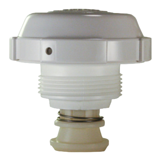
FIG. 1
CREAM COLORED CAM
CLIP ON
RETAINER
FIG. 2
NOTCHES
FIG. 3
HOLE ON COVER
CLIP ON NOZZLE
RETAINER
INSTALLATION GUIDE:
SWINGJET
1. NEW SWING JET
• The swing jet comes packed with the cover off.
• Push the nozzle up and look and feel for the raised area on the side
of the colored nozzle that is in the center of the cream colored Cam.
(Fig 1). The nozzle jet opening is 180 degrees opposite that raised
RAISED
area. Push the nozzle shaft up and down until the nozzle jet is either
AREA
all the way right or all the way left so when you are doing the next two
steps you are aware of which direction it is going to travel when rotat-
ing.
• There are three notches in the cream colored cam above the raised
area (Fig 2). These cam notches are in a straight line with the cam
notches on the opposite side of the raised area. The jet opening of
the nozzle goes back and forth covering the 90 degree arc formed
by the three ratchet positions as the nozzle extends and retracts
when cycled.
• Put one wrap minimum of Teflon tape on the threads to make the
nozzle threads not seize up over time, and thread the swing jet in the
return fitting tight, using the swing jet installation and removal tool. It
should be tight enough so it can not be turned by hand. Hand tighten
only, NEVER USE A WRENCH DIRECTLY ON THE SWING JET. AL-
WAYS REMOVE THE COVER AND USE THE TOOL (Fig. 4) (AVAIL-
ABLE FROM PARAMOUNT 005-720-4508-00) TO COVER THE
SWING JET RETAINER BEFORE USING A WRENCH TO REMOVE
THE SWINGJET.
www.1Paramount.com 1.800.621.5886
Advertisement

Related Manuals for Paramount Fitness SwingJet

Summary of Contents for Paramount Fitness SwingJet
- Page 1 INSTALLATION GUIDE: SWINGJET 1. NEW SWING JET FIG. 1 CREAM COLORED CAM • The swing jet comes packed with the cover off. • Push the nozzle up and look and feel for the raised area on the side of the colored nozzle that is in the center of the cream colored Cam. (Fig 1). The nozzle jet opening is 180 degrees opposite that raised RAISED area. Push the nozzle shaft up and down until the nozzle jet is either AREA all the way right or all the way left so when you are doing the next two CLIP ON RETAINER steps you are aware of which direction it is going to travel when rotat- ing. FIG. 2 • There are three notches in the cream colored cam above the raised area (Fig 2). These cam notches are in a straight line with the cam notches on the opposite side of the raised area. The jet opening of the nozzle goes back and forth covering the 90 degree arc formed by the three ratchet positions as the nozzle extends and retracts when cycled. NOTCHES • Put one wrap minimum of Teflon tape on the threads to make the nozzle threads not seize up over time, and thread the swing jet in the return fitting tight, using the swing jet installation and removal tool. It...
- Page 2 FIG. 4 placed the pins in. (Fig 1) • Once in position find the clip on the outside ring of the nozzle retainer (Fig 1) and place the hole in the cover so it is just to the counter clock wise side of the retainer clip (Fig 3) Line up the notches on the cover with the locking cams on the nozzle retainer. Push the cover on to the retainer and rotate clockwise until the clip snaps in the hole. (Fig 2 & 3). Do not force the cover on when not in position. It will be difficult to remove. 2. ADJUSTING A SWINGJET WHEN IT IS THREADED IN PLACE • Turn the pump on so the Swing Jet is on. If the Swing Jet is on a water valve circuit, wait for the Swing Jet to come on, and pause the FIG. 5 SWINGJET KEY water valve. • Place the swing jet key (Fig 5) provided with the unit (part # 005-721- 4512-00) into the hole on the side of the cover of the swing jet (Fig 3). Leaving the key in place, while pushing down on the key rotate the cover counter clockwise until it stops. Do not remove the key.