Table of Contents
Advertisement
Quick Links
Advertisement
Table of Contents

Related Manuals for Atmos Aqua clean

Summary of Contents for Atmos Aqua clean
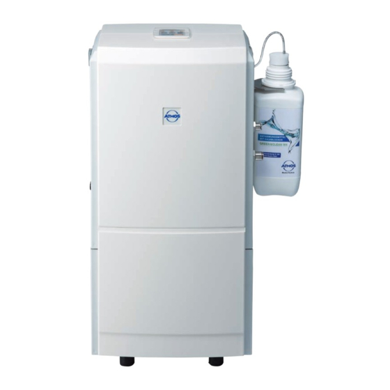
- Page 1 English ATMOS Aqua clean ® Water Supply System GA1GB.110002.0 2018-05 Index: 08...
-
Page 2: Table Of Contents
Installation in the auxiliary housing ........ 8 Hose connections ............8 3.2.1 Initial connection of the chemical bottle ......8 Explanation of the controls ..........9 Connection conditions for ATMOS S 61 Servant ..10 ® Connection conditions for irrigation and stimulation devices ................11 Cleaning and disinfection ......... -
Page 3: Introduction
Repair work and period tests may be carried out only by expert personnel authorised by ATMOS. By applying only original spare parts you will have the guarantee that operational safety, readiness for work and the value of your ATMOS Aqua clean will be preserved. -
Page 4: Function
In the mixing container, the water inlet is in the form of a cascade , ensuring that the ATMOS Aqua clean is ® separated from the water supply, as required by the DVGW (The German Gas and Water Association) (DIN 1988, Part 4). -
Page 5: Scope Of Supply
● Only transport the device in a shipping carton, which is padded and offers sufficient protection. If damage occurs during transport: ● Document and report the transport damage. ● Send the device to ATMOS, see chapter „5.2 Sending in the device“ on page 14. ● Ambient conditions: Transport/Storage: +5...+40 °C;... -
Page 6: Explanation Of Pictures And Symbols
Pictures contained in this manual Proper disposal Warning, Important notes especial diligent notice! Symbols of the ATMOS Aqua clean ® The CE sign shows that this Serial number product meets the appropriate requirements of the EC Directive Order number 93/42 EEC. -
Page 7: For Your Safety
• if obvious defects might restrict safe operated again until it has been checked by operation. the customer service centre. Clean the device and send it in to ATMOS or to your dealer. ● The unit must be set up on a firm, level surface. -
Page 8: Setting Up And Starting
2. Switch on ATMOS S 61 Servant ® Fig. 3 3. Switch on ATMOS Aqua clean ® If error “F1” appears, switch the ATMOS S 61 Servant ® off and on, until the error disappears. Hose connections Chemical bottle connection PVC tubing Ø... -
Page 9: Explanation Of The Controls
Control light 2: Fault (red) Control light 3: Disinfectant sensor (yellow) Alarm RESET button Switch On/Checking routine: The green control signal (Fig. 6) jitters: During the system is switched on the ATMOS Aqua clean ® automatically performs a checking routine. While this Fig. 5 procedure the control signal (Fig. -
Page 10: Connection Conditions For Atmos ® S 61 Servant
1. Open main water tap 2. Switch on ATMOS S 61 Servant ® 3. Switch on ATMOS Aqua clean ® If error “F1” appears, switch the ATMOS S 61 Servant ® off and on, until the error disappears. Fig. 11... -
Page 11: Connection Conditions For Irrigation And Stimulation Devices
Starting Sequence: Fig. 12 1. Open main water tap 2. Switch on irrigation and stimulation device 3. Switch on ATMOS Aqua clean ® If error “F1” appears, switch the irrigation and stimu- lation device off and on, until the error disappears. -
Page 12: Cleaning And Disinfection
Please note that only ATMOS Green & Clean WK ® provides the concentration required for broadspectrum disinfection. The use of chemicals other than from ATMOS may damage the ATMOS Aqua clean as well as other devices which are ® connected. -
Page 13: Care And Cleaning
Then the green control signal 1 jitters slowly. Supply container and pressure container are empty if no more water comes out of the unit. Now, the ATMOS Aqua clean can ® either be switched off or the normal operation can be activated by holding down the RESET button for another 8 sec. -
Page 14: Maintenance
ATMOS. • No warranty rights shall exist in the event of damage or failure caused by the use of non-ATMOS accessories or non-ATMOS consumables. • Check hoses and connections on any leakages at regular intervals. -
Page 15: Retrofitting
Retrofitting at ATMOS S 61 Servant ® For retrofitting at the ATMOS S 61 Servant the product, ® REF 530.2120.N is required. Scope of supply: Article description ATMOS Aqua clean 530.2121.0 1 piece ® Hose clip 061.0060.0 2 pieces Hose clip 061.0061.0 2 pieces Pressure reducer, mini 502.0955.0... - Page 16 3. Switch on ATMOS Aqua clean ® A Assemble the mounting plate and build it in. B Exchange existing plate against mounting plate If error “F1” appears, switch the ATMOS S 61 Servant ® off and on, until the error disappears.
-
Page 17: Tubing
6.0 Retrofitting 6.1.1 Tubing Article description Length Hose RD.I. 6,0 x 3,0 000.0091.0 1000 mm Hose RD.I. 8,0 x 3,0 005.0020.0 1000 mm Hose, Rilsan RD.A. 8,0 005.0025.0 240 mm Hose, Rilsan RD.A. 6,0 005.0173.0 200 mm Hose, Rilsan RD.A.4,0 005.0026.0 450 mm Hose, Rilsan RD.A.4,0 005.0026.0... -
Page 18: Retrofitting Of A Delay Pcb
6.0 Retrofitting 6.1.2 Retrofitting of a delay PCB Drilling of the holes for the fixing bolts. Place the PCB on the carrier ● plate and mark the drillings. Afterwards drill the holes with a 3.5 mm drill. Screw the 4 bolts M3x10 including washer and locknut. ● Tighten the PCB with 4 lens head screws 3x5. ● Fix the connecting cable (REF 530.2124.0) as per the drawing. ●... -
Page 19: Delayed Switching Circuit For Aquastop
6.0 Retrofitting 6.1.3 Delayed switching circuit for Aquastop... -
Page 20: Water Connections
6.0 Retrofitting 6.1.4 Water connections... -
Page 21: Retrofitting At Atmos ® Servant 5 / 5 C
When drilling the holes for the screwed connection (water in- / outlet into and out of the ATMOS Servant 5 housing) ® it is important to consider the equipment of the ATMOS ® Servant 5 which needs to be retrofitted. Here we can only provide some general information and recommendations because of the many different version currently in use. -
Page 22: Tubing
6.0 Retrofitting 6.2.2 Tubing Fig. 29 6.2.3 Add-on kit heating module existing Fig. 30... -
Page 23: Delayed Switching Circuit For Aquastop Until 2005
6.0 Retrofitting 6.2.4 Delayed switching circuit for Aquastop until 2005... -
Page 24: Delayed Switching Circuit For Aquastop From 2006
6.0 Retrofitting 6.2.4.1 Delayed switching circuit for Aquastop from 2006... -
Page 25: Water Connections Until 2005
6.0 Retrofitting 6.2.5 Water connections until 2005... -
Page 26: Water Connections From 2006
6.0 Retrofitting 6.2.5.1 Water connections from 2006... -
Page 27: Troubleshooting
Troubleshooting Prior to dispatch, the ATMOS Aqua clean was subjected to an extensive functional test. If, nevertheless, a failure should ® appear, you may possibly clear it yourself if you follow these notes: Error Possible reason Troubleshooting Device/pump does not –... -
Page 28: Technical Information
Technical information Structure To ensure that it meets the most stringent in-service requirements, the ATMOS Aqua clean consists of several ® modules: Module 1 - Electronic control system. Module 2 - Pressure container; this generates the water pressure. In addition to the container, this module contains a magnetic valve, a pressure-sensitive switch and a non-return valve. -
Page 29: Electrical Connections, Control Pcb
Technical 9.2 Electrical connections, circuit board Overflow sensor (yellow) Pressure-sensitive switch (red) Mixing container probe (yellow/red/black) Disinfectant sensor (green) Level monitor in the pressure container (blue) Air cushion valve on the pressure container (black) MV4 External display Chemical valve (black) MV3 Water safety valve 5 (brown) Pump motor connection Membrane breaking (yellow) Power supply plug 24 V AC (orange) -
Page 30: Technical Specifications
Maximum power consumption: 0.8 A Permitted water pressure: 2-6 bar Operating pressure (water): 2.2 bar Operating pressure (air): 4 bar Maximum water flow rate: 550 ml/min Water quality: drinking water Disinfectant: ATMOS Green & Clean WK ® Hydrogen peroxide, 2% solution Mixing ratio: 1:85 standard setting... -
Page 31: Disposal
In order to guarantee a proper disposal of your old device, please either pass on your old device to your specialised dealer or send it directly to ATMOS MedizinTechnik for a professional disposal. Prior to disposal the device surface must be disinfected. -
Page 32: Notes On Emc
12.1 Guidelines and Manufacturer‘s Declaration - Emissions The ATMOS Aqua clean is intended for use in the electromagnetic environment specified below. ® The customer or user of the ATMOS Aqua clean should ensure that it is used in such an environment. ® Emissions Test Compliance Electromagnetic Environment - Guidance RF Emissions... - Page 33 12.3 Guidelines and Manufacturer´s Declaration - Immunity The ATMOS Aqua clean is intended for use in the electromagnetic environment specified below. The customer or ® user of the ATMOS Aqua clean should ensure that it is used in such an environment. ® IEC 60601- Electromagnetic Environment - Immunity Test Compliance Level...
- Page 34 RF Communications equipment and the ATMOS ® Aqua clean as recommended below, according to the maximum output power of the communications equipment. Separation distance, depending on transmit-frequency m Nominal output of the...
- Page 35 For your notes...
- Page 36 ATMOS MedizinTechnik GmbH & Co. KG Ludwig-Kegel-Straße 16 79853 Lenzkirch / Germany Phone: +49 7653 689-0 atmos@atmosmed.de www.atmosmed.com...
Need help?
Do you have a question about the Aqua clean and is the answer not in the manual?
Questions and answers