Table of Contents
Advertisement
Quick Links
INSTRUCTION
MANUAL
DISTRIBUTOR
Thank you for selecting another fine
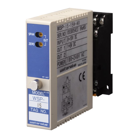
check the description given on the rating label of this unit to make sure
that it meets your specifications and be sure to read this instruction manual
before using the product.
This manual outlines the operation, connection and adjustment procedures
of this product.
The unit has been manufactured and inspected according to our strict
quality control standard. If you should find a defect including damage
incurred during transportation, contact us or the dealer where you
purchased it immediately.
○PACKAGE INCLUDES:
・Distributor..................................1
・Base socket.................................1
* For details of models and specifications, please download the product
catalog from our website, and then check it.
1. PRECAUTIONS
1) Conformity with CE directive
・ This equipment is compliant with Installation Category II and
Pollution Degree 2 environment. The insulation capability between
signal input and output is basic insulation. Before installing, please
check that the insulation class of this equipment satisfies your system
requirements.
・ Please be sure to install this equipment to the inside of a panel.
・ Please use this equipment at an altitude of up to 2000 m.
・ Compliance with EN standards:
EN61326-1
EMS: Industrial environments; EMI: Class A
The wiring length should be not more than 30 m.
EN61010-1
EN50581
* Custom-made items other than a catalog standard specification are
outside CE conformity.
2) Power supply
・ Check the rated voltage on the rating label, and use the product
within the range of each of the following ratings (
the rating label.)
① 100 to 240VAC
100 to 240VAC ±10% (50/60 Hz) approx. 5.4 VA
② 24VDC
24VDC ±10% approx. 95 mA
* You can use it as 21.6 to 30 V, if you do not use this product as a
CE compliant article.
③ 110VDC
110VDC ±10% approx. 18mA
3) Handling
・ When removing or mounting the main body from/to the socket, be
sure to turn OFF the power supply and the input signal in advance to
prevent any problems.
4) Installation
・ This equipment is designed for indoor use.
・ Please install the main body in a location where the ambient
temperature is within -5 to 55°C.
・ Please install the main body in a location where relative humidity is
less than 90%RH (no freezing or condensation).
・ When the equipment is to be installed in a location where there is
excessive dust or metal particles, house it in a dust-proof cabinet,
which has a heat radiation function.
・ Avoid exposing the equipment to vibration and impact, which may
cause malfunction.
・ Please do not block ventilation openings of the main body.
5) Wiring
WSP-DBZ
product. Please
6) Others
2. OUTLINE DIMENSIONS
4. NAME OF EACH PART AND
is indicated on
Terminal No.
Connection points
Screw tightening torque
※1 Please do not wire anything at NC terminal.
6-16-19, JINGUMAE, SIBUYA-KU, TOKYO 150-0001, JAPAN
1/2
・ Be sure to keep the wiring of the power line, input signal line and
output signal line away from any noise source, relay driving line and
high-frequency line.
・ Avoid clamping these lines together with a noise-superimposed line
or putting them together in the same duct.
・ This equipment can be operated as soon as the power supply is
turned ON. However, for optimum performance, allow 30 minutes of
energizing time.
・ This product is precision equipment. It is therefore recommended
that you periodically calibrate it by performing ZERO and SPAN
adjustments once a year.
3. CIRCUIT DIAGRAM
TERMINAL LAYOUT
Symbol
+
1
TRANS
MITTER
-
3
-
4
COM
2
NC
5
NC
6
NC
8
NC
+
7
OUTPUT-1
-
9
10
U(+)
POWER
11
V(-)
:
M3 SEMS screw
:
Recommended: 0.6 N-m
TEL: +81-3-3400-6147 FAX: +81-3-3409-3156
Contents
Connect 4-20 mA signal from
the transmitter.
(Adjusting terminal)
No Connection (※1)
No Connection (※1)
No Connection (※1)
No Connection (※1)
The signal based on the input/output
specification is output.
Connect the power supply of the rated
voltage.
IM0745-01
Advertisement
Table of Contents

Related Manuals for WATANABE WSP-DBZ

Summary of Contents for WATANABE WSP-DBZ
- Page 1 5) Wiring INSTRUCTION ・ Be sure to keep the wiring of the power line, input signal line and WSP-DBZ output signal line away from any noise source, relay driving line and MANUAL high-frequency line. ・ Avoid clamping these lines together with a noise-superimposed line DISTRIBUTOR or putting them together in the same duct.
- Page 2 7. INSTALATION DIMENSIONS 5. ADJUSTMENT When mounting the product on a wall, refer to the installation dimension Since this equipment has been properly calibrated at the time of shipping, diagram. each trimmer of ZERO and SPAN does not require adjustment as long as The diagram below shows the minimum mounting clearance between the equipment is operated according to the manufacturing specifications.
Need help?
Do you have a question about the WSP-DBZ and is the answer not in the manual?
Questions and answers