Table of Contents
Advertisement
Quick Links
Advertisement
Table of Contents

Related Manuals for Evinox ModuSat XR ECO CHHC

Summary of Contents for Evinox ModuSat XR ECO CHHC
- Page 1 Evinox ModuSat XR ECO CHHC Combined Heating, Hot Water and Cooling 2551868A...
-
Page 2: Table Of Contents
5.2.1 RJ45 Connections ........................19 ModuSat® Connection Board ......................20 Typical ModuSat® Electric Wiring Diagram (Two Evinox ViewSmart Room Controllers) ....21 ViewSmart Room controller connections ..................22 SmartTalk® system wiring ......................23 SETTING INTO OPERATION / COMMISSIONING ..............24 Pre-commissioning checklist ...................... -
Page 3: General Information
GENERAL INFORMATION Application The Evinox ModuSat® CHHC heat interface unit provides instantaneous domestic hot water, indirect space heating and cooling when connected to a district heating and cooling systems. The Evinox ModuSat® CHHC unit requires electrical supply to function. Symbols... -
Page 4: Safety Instructions
Safety instructions The Evinox heat interface unit must be installed, commissioned and maintained by a qualified and competent personnel in accordance with this document as well as national regulations and standards. High temperatures. Take necessary precautions when working on the unit as high operating temperatures may cause severe skin burns. -
Page 5: Technical Features
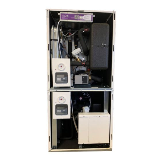
TECHNICAL FEATURES Typical ModuSat® XR & XR-ECO CHHC Unit Note: The product may look different from the image shown. Function and operation District or communal heating system – the primary thermal energy is used to produce domestic hot water and heating. ... -
Page 6: Typical Schematic (All Top Connections)
Typical Schematic (All Top Connections) Components Primary / LTHW flow Primary / LTHW return Domestic cold water Inlet Domestic hot water outlet Secondary heating flow Secondary heating return Connection for safety discharge Primary cooling flow Primary cooling return Secondary cooling return Secondary cooling flow Primary Circuit Side Insulated plate heat exchanger... -
Page 7: Technical Parameters
Technical Parameters Electrical Electric supply 220 / 240 Volt (AC) Frequency 50 Hz Current absorption 0,6-1 Amps Hydraulic connections Type 1 Types 2 & 3 Type 4 Primary LTHW flow 3/4 “ 3/4 “ 3/4 “ Primary LTHW return 3/4 “ 3/4 “... - Page 8 DCW min pressure 1.5 bar Max primary supply temperature 85°C Weight CHHC XR ECO 55-10A-R40 74 kg 79 kg CHHC XR ECO 70-10A-R70 86 kg 93 kg CHHC XR ECO 100-10A-B50 104 kg 113 kg For other models please contact Evinox. 2551868A...
-
Page 9: Typical Dimensions
Typical Dimensions 2551868A... - Page 10 Front: 700 mm, Side: 50 mm. Flushing by pass kits for 1 1/4” are not supplied by Evinox, installer must ensure that there is enough space for the 1 1/4” kit. Please Note: Flushing bypass to be installed on primary connections A & B and A1 & B1.
-
Page 11: Installation
INSTALLATION The Evinox combined heating, hot water and cooling unit must be installed, commissioned and maintained by qualified and competent personnel in accordance with this document as well as national regulations and standards. Handling The unit should be moved into position before lifting still within its packaging to prevent any damage whilst being positioned. -
Page 12: Hydraulic Connections
The ModuSat® heat interface unit is designed to be wall mounted or floor standing with the typical primary connections and domestic water hydraulic connections as shown below. The Evinox Energy flushing by-pass valve kit should be installed before connecting the unit to the network. Isolation valves should not be opened until system is flushed. -
Page 13: Evinox Flushing By-Pass Kit
Evinox Flushing By-pass Kit Evinox flushing by-pass kit allows to isolate HIU from the network during cleaning and flushing the system. The kit includes an H shape by-pass with an inbuilt extended isolation valve, 1 strainer and 5 isolation valves. -
Page 14: Flushing Primary Circuit
Close the bypass after flushing is complete. Provide isolation valves and a strainer. If Evinox valve kit is not used, it must be ensured that other isolation valves provided. Strainer on the primary inlet protects internal components from debris and sediments. Tighten the connections. -
Page 15: Hiu Flushing
Filling the primary circuit Please take care when filling the ModuSat® unit. Make sure that the by-pass valve is in closed position Slowly open the isolation valves on the primary circuit. Visually check that there are no leaks. -
Page 16: Water Treatment
Water treatment The quality and cleanliness of the water within both the primary and secondary circuits is vitally important to prevent damage to the ModuSat® components, and to ensure that the efficiency and service life of the unit is maintained. It is therefore necessary to fully flush and treat both primary and secondary circuits using suitable water treatment chemicals. -
Page 17: Dosing Secondary System
Please confirm with the water treatment consultants that the chemicals used and cleaning method statement complies with the requirements set out in this section. Evinox Energy do not take responsibility for approving inhibitors used for dosing the system. Warranty due to Water Quality The warranty of the ModuSat®... -
Page 18: Electrical Connections
Follow the instructions Any damage caused by an incorrect connection will invalidate the warranty. Evinox Energy cannot accept any responsibility for incorrect wiring. The ModuSat® wiring boards are located within the ModuSat® itself under a removable metal cover. To access the connection board, the full front case cover should be removed. To take off the cover the retaining screw should be removed and the cover lifted off. -
Page 19: Modusat® Wiring Connections
Doing so may invalidate the warranty. Connection Terminations Evinox Energy strongly recommend in accordance with best practice that all wiring connections to the board, especially the BUS and room controller are terminated using ‘bootlace ferrule’ connectors. These connectors ensure a good connection and that the whole cross sectional area of the wiring is intact. -
Page 20: Modusat® Connection Board
ModuSat® Connection Board Please Note: When connecting external valves or pumps to the ModuSat control board, it must be ensured that each connection does not exceed 1amp @ 220/240V (AC). 2551868A... -
Page 21: Typical Modusat® Electric Wiring Diagram (Two Evinox Viewsmart Room Controllers)
Typical ModuSat® Electric Wiring Diagram (Two Evinox ViewSmart Room Controllers) See drawing – STD-MOD-BMS-CHHC_A 2551868A... -
Page 22: Viewsmart Room Controller Connections
ViewSmart Room controller connections The Room controller is a white ABS box with a graphic display. It should be installed in the main living area of the dwelling (if ViewSmart is not used as a thermostat it can be factory fitted on the front case of the CHHC) It must be connected to the connection board within the ModuSat®... -
Page 23: Smarttalk® System Wiring
SmartTalk® system wiring ModuSat® CHHC can be used in two network topologies: RS485 (Bus) and TCP/IP. Typical Modbus system architecture See drawing - STD-MOD-2013-BUS 1 - E Typical TCP/IP system architecture See drawing - STD-MOD-2015-TCP-IP-3 2551868A... -
Page 24: Setting Into Operation / Commissioning
SETTING INTO OPERATION / COMMISSIONING Evinox Commissioning Engineers The unit should be commissioned by Evinox Energy commissioning engineers to validate the warranty unless otherwise specified by Evinox Energy. System Checklist Prior Commissioning It is important that the system is fully ready for the works to be carried out. -
Page 25: Setting Unit Into Operation
The valve should be set to 125% above the design flow rate. The project specific set-point (if required) can be confirmed by Evinox Energy. Tighten Actuator Connections Ensure that the actuators are tightened to ensure the operation of the unit. -
Page 26: 6.2.2 Heating Pump
6.2.2 Heating Pump Evinox ModuSat® unit has two integrated pumps: cooling and heating. Heating circulation pump is Wilo Yonos Para with Pulse-width modulation (PWM) feature. Wilo Yonos Para Pump LED – Description of Status Indicators Diagnosis Status Remedy Solid green... -
Page 27: Initial Commissioning Procedure
Evinox Technical Personnel Evinox Technical Personnel who will visit the project during the course of the installation and at completion to arrange for final commissioning and calibration, do so to assist the contractor and install team to deal with any questions and queries. -
Page 28: Warranty
Replacement parts are chargeable until passed as faulty by Evinox Energy, when a credit will be provided. Any parts that have failed as a result of poor servicing or misuse will not be covered by our warranty. - Page 29 Any modifications to the appliance will invalidate the warranty. Installation of the Evinox Energy unit should only be carried out by suitably skilled and qualified personnel. If failure occurs due to poor or faulty installation work, this will invalidate the warranty.
-
Page 30: List Of Chhc Models
LIST OF CHHC MODELS CHHC xx-xxx-xxx DHW PHE Heating PHE Cooling PHE TYPE 1 TYPE 3 TYPE 2 (3/4” - 3/4” – 3/4") (3/4” - 3/4” – 1") (3/4” - 3/4” – 1") 30-10A-R20 55-20A-R30 70-30A-R40 30-10A-B30 70-30R-B40 30-10A-R70 30-10A-R30 55-20A-R40 70-30A-R50 30-20A-B30... - Page 31 TYPE 4 TYPE 5 TYPE 6 TYPE 7 TYPE 8 (3/4” - 3/4” – 1 1/4") (1” - 3/4” – 3/4") (1” - 3/4” – 1") (1” - 3/4” – 1") (1” - 3/4” – 1 1/4") 30-10A-B50 30-20R-B70 100-10A-R20 100-10A-R70 100-10A-B30 100-10A-B50...
-
Page 32: Wras Certificate
WRAS CERTIFICATE 2551868A... - Page 33 EARTH Keep Warm Facility and DHW cylinder schedules 220/240 VOLTS (AC) MAINS FROM UNSWITCHED 240 V CABLE FUSE 3 AMP When Evinox ViewSmart is used, P2-C connection is not needed for 3.15 AMP 3.15 AMP FUSE FUSE UNSWITCHED KWF control. P2-C only to be used for 3rd party controller to enable FUSED SPUR Keep Warm Facility or DHW cylinder schedules.
- Page 34 MODUSAT SmartTalk DATA LOGGER AND SUPPLY UNIT BUS PRINCIPLE SYSTEM ARCHITECTURE DRAWN CHECKED DATE SCALE AUGUST 2016 N.T.S DRAWING No EVINOX RESERVES THE RIGHT TO MODIFY ANY CHARACTERISTICS OF ITS EQUIPMENT STD/MOD/2013/BUS 1 WITHOUT PRIOR NOTICE AS PART OF ITS CONTINUING PRODUCT DEVELOPMENT...
- Page 35 TITLE TYPICAL TCP / IP NETWORK FOR MODUSAT SYSTEM DRAWN CHECKED DATE SCALE JAN. 2015 N.T.S. DRAWING No EVINOX RESERVES THE RIGHT TO MODIFY ANY CHARACTERISTICS OF ITS EQUIPMENT STD-MOD-2015-TCP/IP-3 WITHOUT PRIOR NOTICE AS PART OF ITS CONTINUING PRODUCT DEVELOPMENT...
Need help?
Do you have a question about the ModuSat XR ECO CHHC and is the answer not in the manual?
Questions and answers