Evinox ModuSat XR Installation Manual
Twin plate heat interface unit
Hide thumbs
Also See for ModuSat XR:

Related Manuals for Evinox ModuSat XR


Summary of Contents for Evinox ModuSat XR
- Page 1 Evinox ModuSat XR (Eco) Twin Plate Heat Interface Unit Installation Manual 2551868AB...
-
Page 2: Table Of Contents
ModuSat® Wiring Connections ..................23 5.2.1 RJ45 Connections ..................... 23 ModuSat® Connection Board................... 24 Typical ModuSat® Electric Wiring Diagram with 2 Zone Control (2 Evinox ViewSmart Room Controllers) ........................25 ViewSmart Room controller connections ................ 26 SmartTalk® system wiring ....................27 SETTING INTO OPERATION / COMMISSIONING ............ - Page 3 WARRANTY ......................... 33 KIWA CERTIFICATE ....................... 35 2551868AB...
-
Page 4: General Information
GENERAL INFORMATION Application The Evinox ModuSat® XR heat interface unit provides instantaneous domestic hot water and indirect space heating when connected to a district or communal heating system. The Evinox ModuSat® XR unit requires electrical supply to function. Symbols IMPORTANT NOTE REGARDING CORRECT INSTALLATION... -
Page 5: Safety Instructions
Safety instructions The Evinox heat interface unit must be installed, commissioned and maintained by qualified and competent personnel in accordance with this document as well as national regulations and standards. High temperatures. Take necessary precautions when working on the unit as high operating temperatures may cause severe skin burns. -
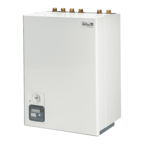
Page 6: Technical Features
TECHNICAL FEATURES Typical ModuSat® XR & XR-ECO Unit Note: The product may look different from the image shown. Function and operation District or communal heating system – the primary thermal energy is used to produce domestic hot water and heating. ... -
Page 7: Typical Schematic (All Top Connections)
Typical Schematic (All Top Connections) ModuSat XR (ECO) Components Primary / LTHW flow Primary / LTHW return Secondary / Domestic cold water Inlet Secondary /Domestic hot water outlet Secondary / Apartment heating flow Secondary / Apartment heating return Connection for safety... -
Page 8: Technical Parameters
Max supply temperature (Primary) 85°C Mass XR ECO TP-30-10R 34.5 kg 36.5 kg XR ECO TP-55-10R 35 kg 37.5 kg XR ECO TP-70-10A 37 kg 39.5 kg XR TP-100-10A 43 kg 47.5 kg For other models please contact Evinox. 2551868AB... -
Page 9: Connection Configurations
Connection Configurations The ModuSat® XR heat interface unit comes with a variety of connection combinations to ease the installation and the aesthetics of the installation. Please find the options below. – Primary flow (in) – Cold water (in) – Secondary heating flow (out) –... -
Page 10: Typical Dimensions (Connection Configurations Shown)
Typical Dimensions (connection configurations shown) TL1 – ModuSat® XR Twin Plate 30/55/70-… & XR-ECO 30/55/70-… All Top Connections HIU Connections: A, B, C, D, E, F: 3/4’’ BSPP male thread. G: 1/2’’ compression. Minimum space requirements for access and servicing: Top: 190 mm (To allow for H-type flushing by pass), Front: 700 mm, Side: 50 mm, Bottom: Sufficient space to connect the drain. - Page 11 TL7 – ModuSat® XR Twin Plate 30/55/70-… & XR-ECO 30/55/70-… Primary Flow & Return and DHW Connections Top. Cold Water Inlet and Secondary Heating Flow & Return Connections at the Bottom HIU Connections: A, B, C, D, E, F: 3/4’’ BSPP male thread.
- Page 12 BL4 – ModuSat® XR Twin Plate 30/55/70-… & XR-ECO 30/55/70 All Connections at the Bottom HIU Connections: A, B, C, D, E, F: 3/4’’ BSPP male thread. G: 1/2’’ compression. Minimum space requirements for access and servicing: Bottom: 190 mm (To allow for H-type flushing by pass) or more if required for connecting the drain and a strainer valve, Front: 700 mm, Side: 50 mm.
- Page 13 TL5 - XR 100-XX All Top Connections But Heating Flow & Return Bottom HIU Connections: A, B, C, D: 1’’ BSPP male thread. E, F: 3/4’’ BSPP male thread. G: 1/2’’ Compression. Minimum space requirements for access and servicing: Top: 250 mm (To allow for H-type flushing by pass), Front: 700 mm, Side: 50 mm, Bottom: Sufficient space to connect the drain and a strainer valve.
-
Page 14: Installation
INSTALLATION The Evinox heat interface unit must be installed, commissioned and maintained by qualified and competent personnel in accordance with this document as well as national regulations and standards. Handling The unit should be moved into position before lifting still within its packaging to prevent any damage whilst being positioned. -
Page 15: Hydraulic Connections
The manufacturer cannot accept any responsibility for any damage caused to the unit due to crossed connections. Any Evinox engineer callout/visit due to this issue will be chargeable. The ModuSat® heat interface unit is designed... - Page 16 STEP4: To remove the pre-installation rig slide the rig to the left taking all connections off centre, slowly lift and remove. Pre-installation Rig Typical Dimensions for ModuSat XR ECO TP-30/55/70-… 2551868AB...
-
Page 17: Evinox Flushing By-Pass Kit
Evinox Flushing By-pass Kit Evinox flushing by-pass kit allows for isolation of the HIU from the network during cleaning and flushing the system. The kit includes an H shape by-pass with built in extended isolation valve, 2 strainers and 4 isolation valves. -
Page 18: First Fill Of The Hiu
Take caution of hot water Slowly close the isolation valves at the top or bottom of the unit Contact Evinox Energy The ModuSat® pump should not be used for flushing. The pump is integral to the unit and should not be used for flushing and cleaning the system. -
Page 19: First Fill Of Apartment Heating System
First fill of apartment heating system The ModuSat® unit is fitted with a pressure gauge that is mounted in the front panel. This gauge reading should be used when filling the secondary circuit. An external filling loop should be used for filling the secondary circuit with the mains cold water. -
Page 20: Water Quality Guidelines
Please confirm with the water treatment consultants that the chemicals used and cleaning method statement complies with the requirements set out in this section. Evinox Energy do not take responsibility for approving inhibitors used for dosing the system. 2551868AB... -
Page 21: Warranty Due To Water Quality
Warranty due to Water Quality The warranty of the ModuSat® unit is strictly related to the instructions and procedures indicated in this manual and the warranty does not cover any damage caused by scale and/or corrosion resulting from poor water quality. The components and materials used in the system assembly should also be checked to ensure they do not contribute to dissolved oxygen that can cause corrosion. -
Page 22: Electrical Connections
Follow the instructions Any damage caused by an incorrect connection will invalidate the warranty. Evinox Energy cannot accept any responsibility for incorrect wiring. The ModuSat® wiring board is located within the ModuSat® itself under a removable metal cover. To access the connection board, the full front case cover should be removed. The connection board is found at the top of the unit to your right. -
Page 23: Modusat® Wiring Connections
Doing so may invalidate the warranty. Connection Terminations Evinox Energy strongly recommend in accordance with best practice that all wiring connections to the board, especially the BUS and room controller are terminated using ‘bootlace ferrule’ connectors. These connectors ensure a good connection and that the whole cross sectional area of the wiring is intact. -
Page 24: Modusat® Connection Board
ModuSat® Connection Board Please Note: When connecting external valves or pumps to the ModuSat control board, it must be ensured that each connection does not exceed 1amp @ 220/240V (AC). 2551868AB... -
Page 25: Typical Modusat® Electric Wiring Diagram With 2 Zone Control (2 Evinox Viewsmart Room Controllers)
Typical ModuSat® Electric Wiring Diagram with 2 Zone Control (2 Evinox ViewSmart Room Controllers) See drawing – STD-MOD-BMS 2551868AB... -
Page 26: Viewsmart Room Controller Connections
ViewSmart Room controller connections The Room controller is a white ABS box with a graphic display. If ViewSmart is not installed on the unit, it should be installed in the main living area of the dwelling. It must be connected to the connection board within the ModuSat®... -
Page 27: Smarttalk® System Wiring
SmartTalk® system wiring Typical Modbus system architecture See drawing - STD-MOD-2013-BUS 1 - E Typical TCP/IP system architecture See drawing - STD-MOD-2015-TCP-IP-3 2551868AB... -
Page 28: Setting Into Operation / Commissioning
SETTING INTO OPERATION / COMMISSIONING Evinox Commissioning Engineers The unit should be commissioned by Evinox Energy commissioning engineers to validate the warranty unless otherwise specified by Evinox Energy. System Checklist Prior Commissioning It is important that the system is fully ready for the works to be carried out. -
Page 29: Pressure Independent Control Valve
The valve should be set to 125% above the design flow rate. The project specific set-point (if required) can be confirmed by Evinox Energy. Tighten Actuator Connections Ensure that the actuators are tightened to ensure the operation of the unit. -
Page 30: 6.2.1 Pump
6.2.1 Pump Evinox ModuSat® unit has an integral Wilo Pulse-width modulation (PWM) circulation pump. Please note: When the unit is switched over to heating mode the pump will run for 2 mins prior to the heating PICV opening, this is not a fault in the unit but a normal control function as the HIU assesses the current heating circuit flow temperature. -
Page 31: Available Pump Head
The below graphs show the available pump head for different ModuSat® models depending on the secondary flow rate. The secondary apartment pressure drop (excluding the unit) should not exceed the value shown. ModuSat XR/XR-ECO XX-10 ModuSat XR/XR-ECO XX-20 Flow rate l/s... -
Page 32: Initial Commissioning Procedure
Evinox Technical Personnel Evinox Technical Personnel who will visit the project during the course of the installation and at completion to arrange for final commissioning and calibration, do so to assist the contractor and install team to deal with any questions and queries. - Page 33 Replacement parts are chargeable until passed as faulty by Evinox Energy, when a credit will be provided. Any parts that have failed as a result of poor servicing or misuse will not be covered by our warranty.
- Page 34 Any modifications to the appliance will invalidate the warranty. Installation of the Evinox Energy unit should only be carried out by suitably skilled and qualified personnel. If failure occurs due to poor or faulty installation work, this will invalidate the warranty.
- Page 35 KIWA CERTIFICATE 2551868AB...
- Page 36 1AMP Keep Warm Facility and DHW cylinder schedules OUTPUT 1 When Evinox ViewSmart is used, P2-C connection is not needed for KWF control. P2-C only to be used for 3rd party controller to enable 240 V CABLE Keep Warm Facility or DHW cylinder schedules. P2-C can also be used for 2nd pulse meter.
- Page 37 MODUSAT SmartTalk DATA LOGGER AND SUPPLY UNIT BUS PRINCIPLE SYSTEM ARCHITECTURE DRAWN CHECKED DATE SCALE AUGUST 2016 N.T.S DRAWING No EVINOX RESERVES THE RIGHT TO MODIFY ANY CHARACTERISTICS OF ITS EQUIPMENT STD/MOD/2013/BUS 1 WITHOUT PRIOR NOTICE AS PART OF ITS CONTINUING PRODUCT DEVELOPMENT...
- Page 38 TITLE TYPICAL TCP / IP NETWORK FOR MODUSAT SYSTEM DRAWN CHECKED DATE SCALE JAN. 2015 N.T.S. DRAWING No EVINOX RESERVES THE RIGHT TO MODIFY ANY CHARACTERISTICS OF ITS EQUIPMENT STD-MOD-2015-TCP/IP-3 WITHOUT PRIOR NOTICE AS PART OF ITS CONTINUING PRODUCT DEVELOPMENT...
Need help?
Do you have a question about the ModuSat XR and is the answer not in the manual?
Questions and answers