Table of Contents
Advertisement
Quick Links
Advertisement
Table of Contents

Related Manuals for Vetek TI-500 E


Summary of Contents for Vetek TI-500 E
-
Page 1: Introduction
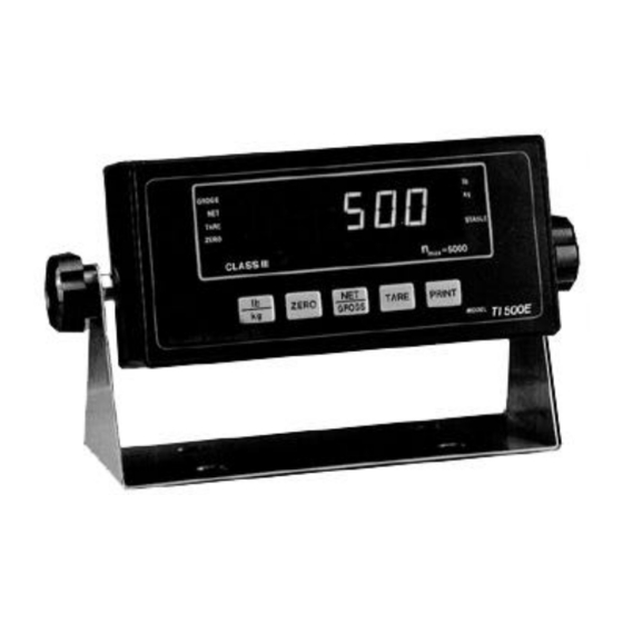
INSTRUCTION MANUAL WEIGHING INDICATOR TI-500 E Manual_TI-500E_V1... -
Page 2: Table Of Contents
Table of Contents Introduction............................1 Keyboard Functions..........................2 Installation and Wiring ........................3 Configuration ............................3 Setup Menu Descriptions........................6 User Menu Descriptions ........................7 Calibration ............................9 APPENDIX A: Specifications......................13 APPENDIX B: Serial Port Modes & Cable Diagrams ................14 APPENDIX C: Determining Proper Span Gain ................... -
Page 3: Installation And Wiring
Installation and Wiring Following is the Installation and Wiring directions for the standard TI-500/500E indicator only. If the indicator was ordered in the stainless steel enclosure, please refer to Appendix D for wiring information. The TI-500's back cover comes equipped with a female DSUB-9 connector for the RS-232 serial port, Setup/Calibration Power Switch... - Page 4 Configuration / Continued To place the unit in Setup menu mode: Note: If the indicator was ordered in the stainless steel enclosure, please refer to Appendix D for instructions on how to enter setup mode. 1. Turn the power off to the unit. 2.
- Page 5 Configuration / Continued To place the unit in User menu mode: 1. Turn the power off to the unit. 2. While holding down the lb/kg key, turn the power back on. 3. When the display shows "A1", the unit is in User Menu mode, and you can release the lb/kg key.
-
Page 6: Setup Menu Descriptions
Setup Menu Descriptions NAME/CODE DESCRIPTION CODE/VALUE Specifies number of full scale graduations. Value should be consistent with 1,000 Graduations legal requirements and environmental limits on the useful system resolution. 1,500 2,000 2,500 3,000 4,000 5,000? 6,000 8,000 10,000 12,000 20,000 30,000 40,000 50,000 Span Gain is related to A/D integration time. -
Page 7: User Menu Descriptions
Setup Menu Descriptions / Continued NAME/CODE DESCRIPTION CODE/VALUE Places indicator into the span calibration routine. Scrolling down with the Press ZERO key to Span Calibration ZERO key one level begins the procedure. begin sequence Actuates the function which allows user to view both the zero and span Press ZERO key to View Calibra- calibration value. - Page 8 User Menu Descriptions / Continued NAME/CODE DESCRIPTION CODE/VALUE Selects the mode of the RS-232C serial port: Serial Port "0" = Full Duplex Mode Mode "1" = Gross/Net/Tare Print Mode Allows the ID No. to be disabled in the Gross/Net/Tare printout. Valid only ID No.
-
Page 9: Calibration
Calibration Note: If the indicator was ordered in the stainless steel enclosure, please refer to Appendix D for instructions on how to enter Setup mode. Setup/Calibration Power Switch Switch LOAD CELL DC Jack RS 232 Connector The indicator is calibrated by following the procedures both calibration values, which can be viewed by embedded in F16 (Zero) and F17 (Span) of the Setup entering the F18 View procedure. - Page 10 Calibration / Continued To calibrate the span using the F17 span calibration procedure: 1. While in the Setup mode, scroll to "F 17", then scroll down once using the ZERO key to enter span calibration menu. 2. The display will momentarily show "C 1" for the span calibration, followed by a value with one flashing digit. This value will be zero with the Decimal Point parameter selected in F10.
- Page 11 Calibration / Continued To record the calibration values using the F18 View Procedure: Note: The values displayed in this procedure are valid only after a successful calibration has been performed using F16 and F17. 1. If the unit is not in the Setup mode, enter the Setup mode as follows: Turn the power off to the unit. On the back cover, move the Setup / Calibration Switch to opposite position.
- Page 12 Calibration / Continued To key-in the span calibration value using the F20 Key-in Procedure: Note: This procedure is intended for emergency use only in the case of non-volatile memory loss. A valid span calibration value, obtained from a successful F17 calibration procedure, must be used. 1.
-
Page 13: Appendix A: Specifications
APPENDIX A: Specifications ANALOG SPECIFICATIONS Full Scale Input Signal 30mV, including dead load 0.4 ? V / grad Minimum Sensitivity - Non H-44 1.0 ? V / grad Minimum Sensitivity - H-44 Input Impedance 30M? , typical Internal Resolution Approximately 260,000 counts Display Resolution 30,000 dd Measurement Rate... -
Page 14: Appendix B: Serial Port Modes & Cable Diagrams
APPENDIX B: Serial Port Modes & Cable Diagrams The TI-500 Indicator is equipped with a full duplex ASCII compatible RS-232 serial communications terminal wired as a female DSUB-9 type connector mounted on the back cover. As shown in A6 of the User Menu, there are two modes of operation –... - Page 15 APPENDIX B: Serial Port Modes & Cable Diagrams / Continued Full Duplex Mode / Continued 1. Recognized host command(s): "P" for Print "Z" to Zero the scale "T" to Tare the scale "G" to change to Gross mode "N" to change to Net mode "C"...
- Page 16 APPENDIX B: Serial Port Modes & Cable Diagrams / Continued To enter a new ID NO. using the A8 ID No. Entry procedure: 1. While in the User Menu mode, scroll to "A 8", then scroll down once using the ZERO key to enter ID No. menu. 2.
-
Page 17: Appendix C: Determining Proper Span Gain
APPENDIX C: Determining Proper Span Gain The Span Gain parameter specified in F2 of the Setup span gain value to use in the Setup Menu for F2. The Menu is directly related to the A/D integration time. first involves looking up a value in the table below, Therefore, the lower the number, the higher the saving that value, then calibrating the system. -
Page 18: Appendix D: Options
APPENDIX D: Options Option A: Stainless Steel Enclosure A) Installation and Wiring OVERVIEW OF TI-500/500E CIRCUIT BOARD 940620 EPROM P+ P- TXD RXD GND E+ S+ E- S- SH Shown above is an overview of the TI-500/500E Circuit Board showing the major landmarks as well as the terminal blocks used for the various inputs and outputs. -
Page 19: Appendix E: Displayed Error Codes
APPENDIX D: Options / Continued Option B: Remote Display If interfacing to a Transcell Technology Remote Display Unit, the following serial communication parameters must be used: Baud Rate (A1): 2400 Data Bits & Parity (A2): 8 Data Bits, No Parity Trans.
Need help?
Do you have a question about the TI-500 E and is the answer not in the manual?
Questions and answers