
Related Manuals for Alarko Carrier AIROStar 39SQ


Summary of Contents for Alarko Carrier AIROStar 39SQ
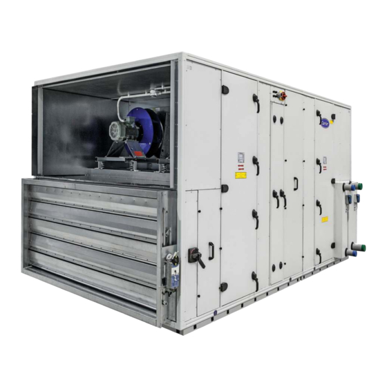
- Page 1 39SQ/39SQR/39SQP Airostar Air Handling Units Installation, operation and maintenance instructions...
-
Page 2: Table Of Contents
CONTENTS 1 - SAFETY CONSIDERATIONS ............................ 3 1.1 - General .................................. .3 1.2 - Applications ................................3 1.3 - Instruction types ..............................3 1.4 - Disposal of parts/materials ............................5 2 - TRANSPORT AND LIFTING INSTRUCTIONS ......................5 2.1 - General .................................. .5 2.2 - Transport and storage ............................ -
Page 3: Safety Considerations
Use of electical equipment with a voltage above 48 V is 1 - SAFETY CONSIDERATIONS only permitted if an earth leakage switch is installed that 1.1 - General complies with local and national regulations. Air Handling unit (AHU) is a device used to regulate and 1.2 - Applications circulate air as part of a heating, ventilating, and air- conditioning (HVAC) system. - Page 4 Rotating parts Central data This pictogram indicates that there are rotating parts This label contains the data for the AHU, such as order behind this access cover, door or panel which may cause number, position number etc. If present, the label is injury.
-
Page 5: Disposal Of Parts/Materials
Opening the fan door This pictogram is positioned on the outside of the door or access cover of the fan assembly. This pictogram warns that the fan must have been switched off and deenergised for a minimum of two minutes before the door or access cover is opened. -
Page 6: Horizontal Transport
For offloading as well as hoisting lifting cables can be 2.5 - Storage attached to the lifting bars. Evenly positioned spacer bars should be used between the lifting cables to prevent The packaging in which the AHU is supplied can cause damage to the top of the unit and ensure that no excess condensation to be formed between the packaging and pressure is applied to the side panels. - Page 7 7. Actuator, extract and supply air damper (2 x) If the customer doesn’t leave sufficient service distance, 8. Main disconnect switch (supply), electric heater Alarko Carrier does not accept any responsibility about commissioning 9. Electrical heater switching components or service problems.
- Page 8 4. Pressure sensor supply/extract/supply air fan (2 x) If the customer doesn’t leave sufficient service distance, 5. Actuator, supply/exhaust air damper (2 x) Alarko Carrier does not accept any responsibility about commissioning 6. Main disconnect switch (supply), electric heater or service problems.
-
Page 9: Checklist Of Start-Up Check Points
3 - CHECKLIST OF START-UP CHECK POINTS 3.1 - Checklist of start-up check points Before commissioning the unit, all functions below and the associated components must be checked, using the check list below. The table below shows a general overview of the planning required to facilitate the installation of the AHU. The following pages give a more detailed description of the individual components. -
Page 10: Start-Up Instructions
4 - START-UP INSTRUCTIONS 4.1.5 - Connected ducts 4.1 - Casing • Inlet and outlet sections could be full face opening or full face damper with flanges. For all fan types The unit data, such as order number, position number etc. (forward, backward or plug) duct have to be fixed is given on the nameplate. - Page 11 • To be able to make two openings one above the other 302/337 or 342/417 mm the corner frames of the two openings have a different length so that there is always enough space to place and attach the profiles. Using the drive slip means that there is no need to use screws in the limited space between the two ducts that are one above the other, as shown in the drawing below.
-
Page 12: Dampers
If a damper is installed on the unit it is recommended to For units that are installed outside the following points must insulate up to the unit (over the damper). The damper can be considered: cause condensation to form on the unit. •... -
Page 13: Air Filters
• Ensure that the end position of the damper is the 4.4.1.1 - Coils containing glycol same as the end position of the actuator so that the drive lever of the damper is unloaded in the end If coils are filled with a water/glycol mixture, this requires position. -
Page 14: Coolers
• The earth warning label is attached to the inside of the 4.4.3 - Electric heater in combination with changeover heater and the inspection hatch. coil For an AHU with control an electric heater combined with a changeover coil can be used. The changeover coil provides primary heating and cooling. -
Page 15: Dx Coils
• Check that the (negative or positive) pressure 4.6 - DX-coils corresponds to the siphon type installed. • The DX-coils are supplied without refrigerant. • The outlet of the siphon trap connected to the drain • The coils must never be pressurised with water. They must not be under pressure. -
Page 16: Plate Heat Exchanger
The following warning sign is shown on the panel. 4.9 - Recirculation damper Rotating parts • Before operating this damper refer to chapter 4.2 • The damper must always be closed at a power failure or when the unit is shut down. •... - Page 17 CAUTION: The air flow may cause stationary parts to move (even a fan that is switched off). • Remove the transport brackets. This is indicated by a label on the door. • Check if the fan can move freely without obstructing the frame, flexible connection or wiring.
- Page 18 Connection diagrams: connection of the power supply cable and of the terminals on the terminal strip Plug fans are equipped with a pressure measurement point 4.10.1 - Plug fans in the intake cone of the fan. By measuring the pressure drop between the pressure for the fan and the pressure in Plug fans are fans without a scroll that are directly driven by the intake cone the actual air flow can be calculated using...
-
Page 19: Silencers
The k-value depends on the fan size used. This value can 4.11 - Silencers be found in the table below. The silencers for the 39SQ are supplied separately on a k-values pallet as duct silencers. For this use the connection profiles Fan size Plug fan recommended and use the method described in chapter in... -
Page 20: Control Panel
4.13 - Control panel Connect the supply voltage to the control panel in accordance with the wiring diagram supplied. The general data for the control panel is given in the table below. Model39 0402 SQR 0506 SQR 0606 SQR 0707 SQR 0402 SQP 0506 SQP 0606 SQP... -
Page 21: Installation Of External Sensors Included
• Check for possible condensate/moisture. Condensate Duct pressure sensor may form in the period before the first start-up of the The active sensor (24 V) has a AHU as a result of weather change and/or humid air maximum measurement range of up from the building. -
Page 22: Sensor Replecament
Thermostat, cooling coil with changeover function The chilled-water coil can be set by the controller to operate as a cooling coil, or a heating coil, if warm water is available for this coil. The controller needs to know if warm or chilled water is available. The passive thermostat supplied for this purpose must be installed on a supply water pipe after this coil. -
Page 23: Maintenance Checklist
5 - MAINTENANCE CHECKLIST 5.1 - Checklist of check points and maintenance intervals The checklist contains a general overview of the planning that facilitates the inspections and maintenance of the AHU. On the following pages there is a more detailed description of the individual components. WARNING: Remember to deenergise all components and to ensure that the fan has stopped rotating, before the doors and access covers are opened before inspections and maintenance take place. -
Page 24: Maintenance And Operating Instructions
6 - MAINTENANCE AND OPERATING INSTRUCTIONS 6.5 - Earthing Ensure that the unit is earthed and installed in the correct 6.1 - General manner. The smooth inside and outside finish of the panels makes 6.6 - Dampers maintenance very simple. Lubrication of the dampers is not required. -
Page 25: Coolers
While working on the heaters gloves must be worn that offer protection against temperatures of 70 °C. The piping outside the air handling unit must be insulated. The water temperature in the pipes can be 120 °C maximum. The following sticker is shown to warn that there is a hot surface. -
Page 26: Plate Heat Exchanger
The following warning pictogram is located on the panel: It is recommended to check the motor and fan bearings for excessive vibration. This can be a sign of bearing wear, but also of incorrect operation of the transmission or an Rotating parts unbalanced system. -
Page 27: Silencers
The warning pictograms indicating rotating parts, electrical 6.15 - Silencers voltage and opening of doors are attached to the door. It is recommended to check the splitters of the silencers periodically for possible damage and loosening of the fibres, to prevent dirt deposits in the system. 6.16 - Control The control must be checked daily for fault messages and alarms. -
Page 28: Open And Closed Instructions
39SQ Air Handling Unit LOCKOUT / TAGOUT 3-board 4-board IMPORTANT • WEAR PERSONEL PROTECTIVE EQUIPMENT WHEN PERFORMING THIS MAINTENANCE. • IF YOU DO NOT TAKE OCCUPATIONAL HEALTH AND SAFETY TRAININGS ACCORDING TO THE RELEVANT NATIONAL LAWS AND OBLIGATIONS PLEASE DO NOT TOUCH THE UNIT. •... - Page 29 39SQ Air Handling Unit LOCKOUT / TAGOUT 3-board 4-board IMPORTANT • WEAR PERSONEL PROTECTIVE EQUIPMENT WHEN PERFORMING THIS MAINTENANCE. • IF YOU DO NOT TAKE OCCUPATIONAL HEALTH AND SAFETY TRAININGS ACCORDING TO THE RELEVANT NATIONAL LAWS AND OBLIGATIONS PLEASE DO NOT TOUCH THE UNIT. •...
- Page 30 Order No.: 13938-11, 07.2016. Supersedes order No.: 13938-11, 07.2014. Manufactured by: Alarko Carrier, Gebze, Turkey. The manufacturer reserves the right to change the specification without prior notice.
Need help?
Do you have a question about the Carrier AIROStar 39SQ and is the answer not in the manual?
Questions and answers