Table of Contents
Advertisement
Quick Links
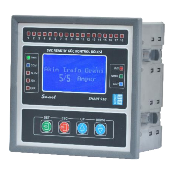
Smart SVC Relay Instruction Manual
GRUP ARGE ENERJİ VE KONTROL
SİSTEMLERİ SAN. ve TİC. LTD. ŞTİ.
İkitelli OSB Mah. YTÜ İkitelli Teknopark Sok.
No: 1/2B1-2B7-2B8-2B9 Başakşehir / İstanbul
Phone : +90 212 438 80 24
Fax : +90 212 438 80 25
Technical Support:
Phone: +90 212 438 61 17
Mobile Phone: +90 542 557 63 22
info@gruparge.com
www.gruparge.com
www.enerjitakibi.com
WARNING: THIS INSTRUCTION MANUAL IS USED FOR RELAYS NAMED;
"SMART S12", "SMART S18",
"SMART S18-T",
"SMART SOG1", "SMART SOG5",
"SMART GES1", "SMART GES5"
Version 19-2
1
Advertisement
Table of Contents


Need help?
Do you have a question about the SMART S12 and is the answer not in the manual?
Questions and answers