Table of Contents
Advertisement
Advertisement
Table of Contents

Related Manuals for Syntron Material Handling BF-4-ALF


Summary of Contents for Syntron Material Handling BF-4-ALF
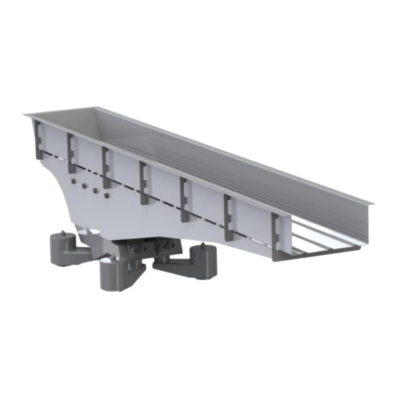
- Page 2 Service Manual Syntron® Electromagnetic Feeder Models: BF-4-ALF and BF-4-ASLF (stainless steel hardware) ■ Installation ■ Operation ■ Maintenance...
-
Page 3: Table Of Contents
TABLE OF CONTENTS Safety Warnings Introduction Inspection and Long Term Storage Theory of Operation Installation Installing the Control Operation Maintenance Spring Replacement Magnet Replacement Air Gap Adjustment Measuring the Stroke Troubleshooting Operating Specifications Parts Diagram Parts List Torque Specifications... - Page 4 Do not operate the unit when Tired, ill, or under the influence of alcohol, drugs or medication. Product safety labels must remain highly visible on the equipment. Establish a regular schedule to check visibility. If you need to replace safety labels, contact Syntron Material Handling for an additional supply free of charge.
-
Page 5: Introduction
Upon receipt, carefully unpack and inspect the feeder for any damage that may have occurred during shipment. If damage is found, contact the shipping carrier and Syntron Material Handling immediately. If the feeder is to be stored for an extended period of time, store it indoors, in its original shipping carton, in a clean, dry area protected from extreme heat. -
Page 6: Installation
The UMC Control and drive unit can be supplied for either 50Hz or 60Hz line freqency operation. CAUTION: Do not operate the BF-4-ALF/ASLF Feeder and control on a supply frreqency other than designated frequency. -
Page 7: Installing The Control
Thebottom spring cup for the coil spring provides for a 1/2-inch (12.5 mm) dia. x 3/4-inch (16 mm) locating pin. Refer to Figure 4 for the outline dimensions of the BF-4-ALF/ASFL Feeder drive. For trough dimensions, refer to the layout drawings provided with the equipment. -
Page 8: Operation
WARNING: Before operating the feeder, be sure the control cover is closed and secured. NOTE: The BF-4-ALF/ASLF Feeder and UMC-30 Control are preset at the factory and do not require adjustment. If a replacement Control or Printed Circuit Board is purchased, they will need to be matched to the feeder as specified in the control instruction manual provided with the Control. -
Page 9: Spring Replacement
trough should be removed daily. Look for buildup at the rear of the feeder trough, particularly around and under the hopper opening. A clean, dry, compressed air supply is recommended for routine cleaning. WARNING: Do not oil the spring assemblies. Oiling the spring assemblies will destroy the clamping effect of the spring pads against one another. -
Page 10: Air Gap Adjustment
1/4 –nch long upper magnet adjusting screw only).). Make sure that the threads on the adjusting screws have been cleaned and Locktite #242 has been applied to the threads. NOTE: Once the magnet assembly has been replaced the air gap will need readjusted. Feeler gauges are used to measure thickness or distance between the magnet and armature. - Page 11 1. Loosen the lower socket head adjustment screw. This is the screw (without the rubber washer) located on the back of the base casting between the rear spring sets. 2. Tighten the upper socket head adjustment screw. This screw is located directly above the lower socket head adjustment screw.
-
Page 12: Measuring The Stroke
MEASURING THE STROKE Feeder stroke can be easily measured with a stroke gauge. BF-4-ALF / ASLF Feeders leave the factory with a correctly positioned metal stroke gauge attached to the side of the trough rib. Refer to Figure 6. While the feeder is operating, the inner lines of the gauge appear as an X, and the stroke should be read at the intersection of the X. -
Page 13: Troubleshooting
TROUBLESHOOTING PROBLEM CAUSE CORRECTION Line voltage is below voltage Increase line voltage as indicated on nameplate designated on the nameplate. Unit in contact with rigid object. Isolate the unit. Spring action may be hampered. Remove and clean spring assemblies Defective leaf springs *Replace. -
Page 14: Operating Specifications
(Ref. Air Gap Range only) (Maximum Trough Weights) BF-4-ALF 110# 1775 235T12 230/60 .160 (.140 MIN.) 1775 515T15 460/60 .160 (.140 MIN.) 1975 275T12 220/230/50 .140 (.120 MIN.) 1975 515T15 380/50 .140 (.120 MIN.) PARTS DIAGRAM – BF-4-ALF / ASLF... -
Page 16: Parts List
PARTS LIST ITEM DESCRIPTION PART NO. Trough Mounting Bracket D-300278 Hex Hd Cap Screw 3/8”-16 UNRC-2A x 3 Lg Gr 5 H0343124 Hex Hd. Cap Screw 3/8”-16 UNRC-2A x 3 Lg (SS) ONLY H0311403 Flat Washer 3/8 Zn. Pl. H0117001 ... -
Page 17: Torque Specifications
PARTS LIST (cont’d) Hex Socket Hd. Cap Screw (3/8”-16 x 1-3/4”)(SS) ONLY H0451302 Isolator Housing D-300531-AA Neoprene Spring Cap 0241X022 Coil Spring 0274X016 Hex Head Cap Scew 3/8”-16 x 1 ½” Zn. Pl. H0310601 Hex Head Cap Scew 3/8”-16 x 1 ½” (SS) Only H0340296 Lockwasher 3/8”... - Page 18 Important This service manual is provided to assist in the operation and maintenance of your Syntron Material Handling LLC equipment. Requests for additional manuals or replacement parts should be directed to the address listed at the end of this page: Please be sure to include the following information when ordering replacement parts: 1.
- Page 19 Corporate Office P.O. Box 1370 Tupelo, Mississippi 38802 Phone: 662.869.5711 Fax: 662.869.7449 Form No. SM0527_122214 Printed in U.S.A Tupelo Changshu 2730 Hwy 145 South #2 Road No. 1 Saltillo, Mississippi 38866 Changshu Export Processing Zone Phone: 662.869.5711 Changshu, Jiangsu, China 215513 Fax: 662.869.7493 Phone: +86 0512.52299002...
Need help?
Do you have a question about the BF-4-ALF and is the answer not in the manual?
Questions and answers