Table of Contents
Advertisement
Make sure you read this instruction manual thoroughly before
installing, wiring, operating and inspecting this SHOCK
RELAY
Please make sure that this instruction manual accompanies the
SHOCK RELAY to the end user.
Please keep this instruction manual safe until this product is
disposed of.
Product specification is subject to change for improvement
without notice.
WARNING
Advertisement
Table of Contents

Related Manuals for Tsubaki TSBED Series

Summary of Contents for Tsubaki TSBED Series
- Page 1 WARNING Make sure you read this instruction manual thoroughly before installing, wiring, operating and inspecting this SHOCK RELAY Please make sure that this instruction manual accompanies the SHOCK RELAY to the end user. Please keep this instruction manual safe until this product is disposed of.
-
Page 2: Table Of Contents
CONTENTS Page Page 10. Function ...……………………..1. Preface ………………………… 11. LED display .……………………….. 2. Safety precaution………..…..12. Set up ……………..…..…..... 3. Checking the package ………… 13. Troubleshooting ..…...…..….….… 4. Dimensions...………………….. 14. Reset procedure for trip operation… 5. Specifications…………………. 15. Maintenance ..…..…..…..… 6. - Page 3 WARNING ●Follow safety related rules and regulations. (Ordinance on Industrial Safety and Health, etc.) ●In the case of installation, removal, maintenance, please follow the below requirements. (1)Power off. (2)To avoid falling accident, do not stand under the device. (3)Tighten moving parts. (4)Wear proper work clothes and protective equipment.
-
Page 4: Checking The Package
3 Checking the package Upon receiving the Shock Relay, please check the following: Check whether the model and specification conform to what you ordered. Check to see no damages occurred during the delivery. Package: Shock Relay, Instruction Manual Model Identification ED series Maximum Motor Capacity (class 200V ) 0.2kW... -
Page 5: Specifications
5. Specifications... -
Page 6: Storage
6. Storage ● Storage shock relay on condition of temperature -30 condensation, freeze, oil mist, to +70 , no CAUTION corrosive gases, and dust If you do not comply with the above storage environment, Shock Relay may not function properly 7. -
Page 7: Wiring
8. Wiring Explanation of the Terminals B Contact Control Power Source (1) Connect to a commercial power supply. Never mistake the voltage of the control power source. If device with harmonic noise, such as inverter is used, install an isolation transformer. (2) When connecting without crimp terminal, tightening torque of 0.4~0.6N m( ) is recommended to avoid screw damage. -
Page 8: Wiring Diagram
9. Wiring diagram Wire passes:2 times Circuit breaker Overcurrent relay Fuse Magnetic contactor Transformer (1) A Transformer may be required, depending on the voltage of Motor. (2) Install an insulation transformer between the power line and terminal A1-A2 of the Shock Relay when harmonic noise is included in the power on. -
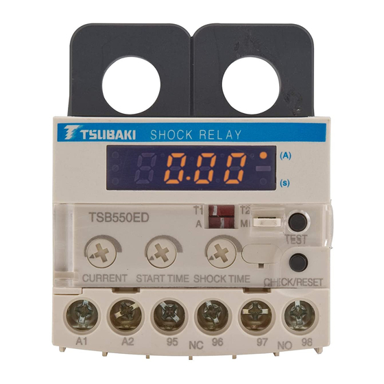
Page 9: Function
Function LED Display ip Switch CHECK/REST/Button Current Level Preset VR Factory default setting MAX fully rihgt Trip level(electric current value) is preset. It changes on the setup screen when a preset VR is turned. Trip relay will be energized when current exceeds CURRENT LEVEL and goes on beyond the Shock Time. - Page 10 Current value and set current are displayed when (A) is indicated Start time and shock time set up are displayed when (s) is indicated Dip Switch setting display and relay movement 95-96 97-9 95-96 97-98 Locked Motor Trip 0.2s 95-96 (Trip) 97-98 (Trip)
-
Page 11: Led Display
11 LED Display Display Power Supply Trip screen Monitor screen During motor stops When motor stops, monitor screen indicates “0.00A” During motor starts(Start time) When motor starts, monitor screen indicates “d” and “d” flickers during the period of Start time. Actual current Actual current shows “5.00”. - Page 12 Set up screen Current Turn VR CHECK/RESET Start time If VR is not turned, display returns to Turn VR Monitor screen CHECK/RESET after 20 sec. Shock time Turn VR CHECK/RESET Monitor screen Trip display Current value exceeded CURRENT setup Check whether after the start time, and went on beyond the there is a wrong...
-
Page 13: Set Up
Set up Setting before the motor start Current Set the rated motor current Start time Set 3 sec Shock time Set minimum data(0.2 sec) Start time setup value 1) Start the motor 2) In case that relay does not operate by above setup value, set shortest value without trip. 3) In case that relay operates, set proper values that relay does not operate. -
Page 14: Reset Procedure For Trip Operation
14. Reset procedure for trip operation (1) Confirm content indication on LED when trip occurs.(Refer to page 8) (2) Confirm if machine, connection and power supply have any abnormal. (3) If there is anything abnormal, remove its roots and set to right situation. (4) In case holding relay output, push Check/Reset button or turn off Shock relay. -
Page 15: Warranty
18.Guarantee Tsubakimoto Chain Co.: hereinafter referred to as “Seller” Customer: hereinafter referred to as “Buyer” Goods sold or supplied by Seller to Buyer: hereinafter referred to as Goods. 18.1 Warranty period without charge Effective 18 months from the date of shipment or 12 months from the first use of Goods, including the installation of the Goods to the Buyer’s equipment or machine –... - Page 16 1-1, Kohtari-Kuresumi, Nagaokakyo TSUBAKIMOTO CHAIN CO. K K yoto 617- 0833, Japan http://tsubakimoto.com/ Internet U.S. Tsubaki Power Transmission, LLC Tsubakimoto Singapore Pte. Ltd. Tsubakimoto Europe B.V. http://www.ustsubaki.com/ http://tsubaki.sg/ http://tsubaki.eu/ Tsubaki of Canada Limited Taiwan Tsubakimoto Co. Tsubakimoto U.K. Ltd. http://tsubakimoto.com.tw/ http://tsubaki.eu/...
Need help?
Do you have a question about the TSBED Series and is the answer not in the manual?
Questions and answers