Table of Contents
Advertisement
Quick Links
Carrier for NVIDIA
Revision No
Release Date
1.01
08/05/2019
1.02
02/25/2020
1.03
03/27/2020
FOR TECHNICAL SUPPORT
PLEASE CONTACT:
Email:
support@diamondsystems.com
STEVIE™
®
AGX Xavier Module
USER MANUAL
Comments
Initial Release
Major Feature Updates. Added Section: Getting Started
Added Addendum
© Copyright 2020
Diamond Systems Corporation
www.diamondsystems.com
Advertisement
Table of Contents

Related Manuals for Diamond Systems STEVIE

Summary of Contents for Diamond Systems STEVIE
- Page 1 AGX Xavier Module USER MANUAL Revision No Release Date Comments 1.01 08/05/2019 Initial Release 1.02 02/25/2020 Major Feature Updates. Added Section: Getting Started 1.03 03/27/2020 Added Addendum FOR TECHNICAL SUPPORT © Copyright 2020 PLEASE CONTACT: Diamond Systems Corporation Email: support@diamondsystems.com www.diamondsystems.com...
-
Page 2: Table Of Contents
3.16 Utility Header Connector ..........................13 3.17 LED Indicators ............................13 Functional Block Diagram ..........................14 Stevie Baseboard Block Diagram ....................... 14 AGX Xavier Series Module Block Diagram ....................15 Mechanical Drawing ............................16 Connector and Jumper Location ......................... 18 I/O Connectors, Jumpers and LED Specifications .................. - Page 3 15.2 Serial Multiprotocol Configuration ....................... 48 15.3 CAN Controller Configuration ........................50 Third-Party Product Guidelines ........................51 16.1 Board Design Considerations ........................51 16.2 Labeling Guidelines ............................ 51 Limited Warranty Policy ..........................53 Stevie User Manual Rev 1.03 www.diamondsystems.com Page 3...
-
Page 4: Important Safe Handling Information
Diamond Systems recommends that all its boards be stored only in individual ESD-safe packaging units. If multiple boards are stored together, they should be contained in bins with dividers placed between the boards. - Page 5 Overvoltage on Analog Input: If a voltage applied to an analog input exceeds the power specification of the board, the input multiplexer and/or parts behind it can be damaged. Most Diamond Systems boards will withstand an erroneous connection of up to 36V on the analog inputs, even when the board is powered off, but not on all boards, and not under all conditions.
-
Page 6: Introduction
Support for the AGX Xavier 8 GB Modules will be provided subsequently. Packaged in an ultra-compact sized form-factor measuring H 3.6” x W 4.13” (92 mm x 105 mm) Stevie baseboard is empowered to deliver the latest technologically innovative breakthroughs by converging Fifth Generation (5G) and Fourth Generation (4G) Networking Technologies. -
Page 7: Agx Xavier Modules Overview
Module (COMs), and Smart devices such as Cameras, within a secure and automotive environment. The circuitry and I/O connectors on the baseboard utilize all available features of the AGX Xavier Series Module to deliver highly versatile performance in industrial environments. Stevie User Manual Rev 1.03 www.diamondsystems.com Page 7... - Page 8 280 Grams (9.87 Ounces) +/- 10 grams with Packaging including Thermal Transfer Weight Plate (TTP) Connector 699-Pin Board-to-Board Connector Cooling Solution Integrated Thermal Transfer Plate (TTP) with Heat Pipe Power Input Range 9.0-20VDC Operating -25°C to +80°C Temperature Range Stevie User Manual Rev 1.03 www.diamondsystems.com Page 8...
-
Page 9: Functional Overview
RJ45 (Registered Jack) network interface for connecting RJ45/Ethernet cables. The LEDs on the RJ45 serve as an activity indicator to indicate the connectivity, link, speed, and data transmission status across the network. Stevie User Manual Rev 1.03 www.diamondsystems.com Page 9... -
Page 10: Display Controller
NOTE: By default, the Elton baseboard does not feature a Debug Serial Console Port but provides the option to set up a Debug Serial Console by mounting the Jumper on J24. This will initiate the Serial Console configuration via serial port 1. Stevie User Manual Rev 1.03 www.diamondsystems.com Page 10... -
Page 11: Pcie/Usb 3.1/Ufs Link Routing Controllers
(HS)-G1, HS-G2, and HS-G3, at both, Rate A and Rate B speeds. MPHY modules drive the physical link and convert parallel data streams from the high-speed serializer into a high-speed differential or low- speed Pulse-Width Modulation (PWM)-like transmissions. Stevie User Manual Rev 1.03 www.diamondsystems.com Page 11... -
Page 12: Pcie Minicard Socket
3.11 USB Ports Stevie baseboard implements four USB 2.0 ports and two USB 3.1 ports. All ports are connected to 1 no. of the 2x5 header. By default, one USB 2.0 port is routed to the 2x5 header and can be switched to the MiniCard socket using the Jumper option explained in Section 3.10: PCIe MiniCard Socket above. -
Page 13: Controller Area Network (Can) Interface
Description Power IN Green LED indicates Power IN Power ON Green LED indicates Power Good Host Green LED indicates a Successful System Boot User Green LED indicates DAQ Controller Chip is ON Stevie User Manual Rev 1.03 www.diamondsystems.com Page 13... -
Page 14: Functional Block Diagram
4 FUNCTIONAL BLOCK DIAGRAM 4.1 Stevie Baseboard Block Diagram The following Block Diagram illustrates the key functional blocks of the Stevie baseboard with integrated NVIDIA AGX Xavier Series Module. Figure 4-1: Stevie Baseboard Functional Block Diagram Stevie User Manual Rev 1.03 www.diamondsystems.com... -
Page 15: Agx Xavier Series Module Block Diagram
The following Block Diagram illustrates a high-level view of the AGX Xavier Series components. The ports are broken out through the carrier board. Figure 4-2: AGX Xavier Series Module Functional Block Diagram Stevie User Manual Rev 1.03 www.diamondsystems.com Page 15... -
Page 16: Mechanical Drawing
5 MECHANICAL DRAWING Figure 5-1 illustrates the top mechanical view of the Stevie baseboard. Figure 5-1: Stevie Baseboard Mechanical Top View Stevie User Manual Rev 1.03 www.diamondsystems.com Page 16... - Page 17 Figure 5-2 illustrates the bottom mechanical view of the Stevie baseboard Figure 5-2: Stevie Baseboard Mechanical Bottom View Stevie User Manual Rev 1.03 www.diamondsystems.com Page 17...
-
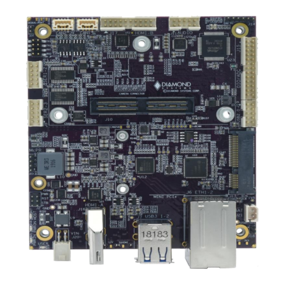
Page 18: Connector And Jumper Location
6 CONNECTOR AND JUMPER LOCATION The following figures display the top, bottom and perspective layouts of the Stevie baseboard. A description of the Jumpers and Connectors is tabulated below. Figure 6-1: Stevie Baseboard Jumper and Connector Layout Top View Stevie User Manual Rev 1.03 www.diamondsystems.com... - Page 19 Figure 6-2: Stevie Baseboard Jumper and Connector Layout Bottom View Figure 6-3: Stevie Baseboard with attached AGX Xavier Module Perspective View Stevie User Manual Rev 1.03 www.diamondsystems.com Page 19...
-
Page 20: O Connectors, Jumpers And Led Specifications
3rd LED HOST LED CAN 1 4th LED SAM User LED CAN 2 Camera Audio M.2 PCIe Mini PCIe Card SAM/Programming Header HDMI-A HDMI-B USB 2.0 Power IN Battery J22 (Bottom) MCU Header Stevie User Manual Rev 1.03 www.diamondsystems.com Page 20... -
Page 21: Connector Pinout Specifications
It serves as an alternate power source when a computer is shut down. The pinouts for the RTC Battery connector are specified below. RTC_BATT Connector Type: 2x1 Header Mating Cable Part Number: 6980524 Stevie User Manual Rev 1.03 www.diamondsystems.com Page 21... -
Page 22: Ethernet Connector: J6
The following illustration depicts the dual receptacle with two USB 3.0 Type-A port pinouts. Connector Type: Standard Stacked USB 3.0/2.0 Receptacle; Type A No. of Positions: 18 Orientation: Right Angle Mounting Type: Through-Hole Stevie User Manual Rev 1.03 www.diamondsystems.com Page 22... -
Page 23: Audio Connector: J11
Mating Cable Part Number for Pin Header: 6981076 8.6 HDMI Connectors: J16, J17 Stevie baseboard integrates two High Definition Multimedia Interface (HDMI) receptacle connectors for transmitting uncompressed video data from an HDMI-compliant device, such as a display controller, to a compatible digital screen in video formats and waveforms. -
Page 24: Usb 2.0 Connector: J19
USB1 Data- A04 B04 USB0 Data- USB1 Pwr+ A05 B05 USB0 Pwr+ Connector Type: Standard 2mm Dual-Row Straight Pin Header Mating Cable Part Number for Latching Connector: 6980602 Mating Cable Part Number for Pin Header: 6981082 Stevie User Manual Rev 1.03 www.diamondsystems.com Page 24... -
Page 25: Camera Expansion Connector: J10
GND 123 124 GND CSI_7_D0_P CSI_5_D0_N 61 62 GND 125 126 GND CSI_7_D0_N GND 63 64 GND 127 128 GND Connector Number: Samtec QSH-060-01-H-D-A-K-TR Mating Connector Part Number: Samtec QTH-060-01-L-D-A Manufacturer: e-Con Systems, Leopard Imaging Stevie User Manual Rev 1.03 www.diamondsystems.com Page 25... -
Page 26: Serial Port Connectors: J4, J5
NC A05 B05 NC Connector Type: Standard 2mm Dual-Row Straight Pin Header with Gold Flash Plating Mating Connector Part Number for Latching Connector: 6980601 Mating Cable Part Number for Pin Header: 6981075 Stevie User Manual Rev 1.03 www.diamondsystems.com Page 26... -
Page 27: Pcie Minicard Connector: J13
PCIe 1 RX+ +1.5V SMB Clk PCIe 1 TX- SMB Data PCIe 1 TX+ +3.3V +3.3V WWAN LED- Ground WLAN LED- WPAN LED- +1.5V Pull-up to +3.3V +3.3V Connector Part Number: MM60-52B1-E1-R650 Stevie User Manual Rev 1.03 www.diamondsystems.com Page 27... -
Page 28: Pcie Ssd Socket (M-Key) Connector: J12
8.11 M.2 PCIe SSD Socket (M-KEY) Connector: J12 Stevie baseboard is equipped with an M-keyed connector. An M.2 SSD is "keyed" to prevent the insertion of a card connector to an incompatible socket on the host. There are three keys that are commonly used: B, M, and B+M with the key type is typically labeled on or near the edge of the gold-plated fingers on the connector of the SSD. -
Page 29: Data Acquisition (Daq) Connector: J15
The following table provides the pinouts for the power utility connector. Force Recovery Ground Reset In Ground Power Button Ground Connector Type: Standard 2mm Dual-Row Straight Pin Header Cable Part Number: TBD Stevie User Manual Rev 1.03 www.diamondsystems.com Page 29... -
Page 30: Can Connectors: J8, J9
The AGX Xavier Series Module supports a x1 lane UFS interface. The pinouts for the connector are specified below. DIN_C DIN_T DOUT_C DOUT_T REFCLK VCCQ2 DATA1 DATA0 DATA3 DATA2 C_DETECT Connector Type: Standard UFS + Micro SD Connector Manufacturer: Amphenol Stevie User Manual Rev 1.03 www.diamondsystems.com Page 30... -
Page 31: O Connector List
9 I/O CONNECTOR LIST The following table provides a summary of the I/O connectors on the Stevie baseboard. Function Manufacturer Part No. Description Mating Cable 2x2 Box Header T/H Right Angle .1” Pitch Power IN Samtec IPL1-102-01-D-RA-K 6981507 External Battery... -
Page 32: Jetson Xavier B2B Connector Interface
10 JETSON XAVIER B2B CONNECTOR INTERFACE The following table figure depicts Jetson AGX Xavier Series Module Connector Pin Out Matrix Part 1: Columns A – F. Stevie User Manual Rev 1.03 www.diamondsystems.com Page 32... - Page 33 The following table figure depicts Jetson AGX Xavier Series Module Connector Pin Out Matrix Part 2: Columns G – L. Stevie User Manual Rev 1.03 www.diamondsystems.com Page 33...
-
Page 34: Jumper Description
Serial Port2 TX Termination Enabled Disabled Serial Port1 RX Termination Enabled Disabled Serial Port2 RX Termination Enabled The following figure illustrates the default Jumper settings on the JP1 block. Figure 11-1: Jumper JP1 Default Locations Stevie User Manual Rev 1.03 www.diamondsystems.com Page 34... -
Page 35: Debug Uart (J24)
The following table shows the position, function, and the states for the MiniCard on the J18 block. The text in bold and italics mark the default configuration. Position Function 2 x 5 Header USB-SEL USB2.0 SEL MiniCard Stevie User Manual Rev 1.03 www.diamondsystems.com Page 35... -
Page 36: Getting Started
Machine and flashed on to the AGX Xavier Series Module. To update the image on the AGX Xavier Series Module, Stevie baseboard must be set to Recovery Mode. This is accomplished by pressing the RCVRY (SW3) button while powering up the baseboard. - Page 37 FTP (File Transfer Protocol) site and copy it to the Linux Host Machine. Figure 12-2: Stevie Release Image File Displayed on Screen To unzip the copied Image file: Type and Enter the following command depicted in the Screen below. It may take a few minutes for the file to unzip.
- Page 38 ./flash.sh jetson-xavier-maxn mmcblk0p1 The flashing process will take 15-20 minutes to complete. NOTE: Do not interrupt or interfere with the USB connectivity or the power supply to Stevie until the flashing procedure is complete. When the flashing is complete, the AGX Xavier Series Module will automatically Reboot.
-
Page 39: Data Acquisition (Daq) Subsystem
13.1 SAM Data Acquisition Circuit Overview Stevie baseboard implements a data acquisition circuit with analog input, analog output, and digital I/O interfaces in conjunction with the NVidia Jetson AGX Xavier Series Module, which integrates a built-in DAQ subsystem supported by the Atmel SAM D51 Microcontroller Series Part No. - Page 40 The conversion formulas between the input voltage and A/D code shown below, are based on the ideal case scenario. A/D Conversion Formulas A/D code = input voltage / 3.3V x 4096 (min value 0, max value 4095) Input voltage = A/D code / 4096 x 3.3V Stevie User Manual Rev 1.03 www.diamondsystems.com Page 40...
- Page 41 All A/D circuits are susceptible to inherent gain and offset errors depending upon factors such as temperature. The SAM circuit calibrates some of these errors to provide better accuracy. The Diamond Systems driver and Programming Library calibrate raw uncorrected data or corrected data with greater accuracy between the A/D input range of 0V and/or 3.3V.
-
Page 42: Analog Outputs
D/A code Hex D/A code Dec Output voltage 0x000 0.0000V 0x001 0.0008V 0x002 0.0016V 0x7FF 2047 1.6592 0x800 2048 1.6500V 0x801 2049 1.6508V 0xFFE 4094 3.2984 0xFFF 4095 3.2992V Stevie User Manual Rev 1.03 www.diamondsystems.com Page 42... -
Page 43: Digital I/O Operations
D51 Microcontroller Package No. TQFP-64 and are applicable when using the microcontroller. The pinout specifications in the table do not apply to the Diamond Programming Library functions since the mapping functions are managed by the software. Stevie User Manual Rev 1.03 www.diamondsystems.com Page 43... - Page 44 PA18 Camera 1.8V enable (Active High) PA19 Camera 2.8V enable (Active High) PA20 Serial Ports 1-2 Config bit 0 PA21 Serial Ports 1-2 Config bit 1 PA15 Serial Ports 1 & 2 Stevie User Manual Rev 1.03 www.diamondsystems.com Page 44...
-
Page 45: Specifications
14 SPECIFICATIONS The Stevie baseboard specifications are summarized in the following table. Feature Module AGX Xavier Series 8-Core ARM v8.2 64-Bit CPU, 8MB L2 + 4 MB L3 16 GB 256-bit LPDDR4x; 2133MHz – 137 GB/s SDRAM Memory Display Two Multi-Mode DP 1.2/eDP 1.4/HDMI 2.0 USB Ports 2x USB 2.0;... -
Page 46: Addendum
The Camera Baseboard (e-CAM30_HEXCUXVR_BASE_BRD) Refer to the e-CAM130_CUXVR_Getting_Started_Manual.pdf. on the Documents page located at the e-con Systems site. for detailed interfacing information. The Adaptor Board : 3. The Dual Board (e-CAM130_TRICUTX2_ADAPTOR e-CAM137_CUMI1335_MOD Stevie User Manual Rev 1.03 www.diamondsystems.com Page 46... - Page 47 An image of the 4-camera installation is depicted below. Power-On the system. NOTE: For a successful implementation ensure that the trigger signal range conforms to 3.3V or 5V. Voltage signals greater than 5V will cause permanent damage to the chip. Stevie User Manual Rev 1.03 www.diamondsystems.com Page 47...
-
Page 48: Serial Multiprotocol Configuration
The SAM D51 microcontroller utility controls all four ports on the SP336 transceiver. The microcontroller utility is used to set the modes for Ports 1 and 2 and the platform GPIOs are used to set the mode for Ports 3 and 4. Stevie User Manual Rev 1.03 www.diamondsystems.com Page 48... - Page 49 After the transmission is complete the RX protocol will be enabled as depicted in the syntax and screen below. #sudo rs485_util ttyTHS<n> 0 Figure 15-2: Enabled RX Protocol Screen The table below lists the GPIO values and transceiver modes. Sysfs GPIO RS232 RS422 RS485 Number Stevie User Manual Rev 1.03 www.diamondsystems.com Page 49...
-
Page 50: Can Controller Configuration
The following command line sends CAN-frames via CAN_RAW sockets. cansend can0 5A1#1122334455667788 candump The command dumps traffic on a CAN network The following syntax shows the received message from the CAN bus. candump can0 Stevie User Manual Rev 1.03 www.diamondsystems.com Page 50... -
Page 51: Third-Party Product Guidelines
16 THIRD-PARTY PRODUCT GUIDELINES The following Guidelines are intended to ensure compliance with DSC Board services when implementing third-party hardware used in conjunction with Diamond Systems boards or components, as part of a solution. 16.1 Board Design Considerations Test Points The board must consist of well-defined and clearly accessible Test Points to enable debugging procedures. - Page 52 Label adhesives must be free of Adhesive Creep –a deformation of adhesive material, which when subjected to physical, mechanical, electrical, and/or environmental pressure, –causes the adhesive to Creep or flow. Stevie User Manual Rev 1.03 www.diamondsystems.com Page 52...
-
Page 53: Limited Warranty Policy
17 LIMITED WARRANTY POLICY Diamond Systems Corporation warrants that its products will be free from defects and errors in material and workmanship and perform in full accordance with the technical specifications stated in the description of the product for a duration of 2-Year Period from the Date of Shipment.
Need help?
Do you have a question about the STEVIE and is the answer not in the manual?
Questions and answers