Table of Contents
Advertisement
Installation, Operation & Maintenance Manual
200 Cabel Street, P.O. Box 3944 Louisville, Kentucky 40201-3944
Email:
Office 800-648-5438
IMPORTANT:
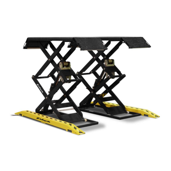
Dual Scissor Lift
M
ODEL
7,700
LBS
3,850
LBS
sales@challengerlifts.com
/
502-625-0700 Fax 502-587-1933
READ THIS MANUAL COMPLETELY BEFORE
INSTALLING or OPERATING LIFT
DX77
. C
APACITY
.
P
PER
AD
Web site:
www.challengerlifts.com
Rev. 01/03/19
Advertisement
Table of Contents

Related Manuals for Challenger Lifts DX77 Series


Summary of Contents for Challenger Lifts DX77 Series
- Page 1 Installation, Operation & Maintenance Manual Dual Scissor Lift DX77 ODEL 7,700 APACITY 3,850 200 Cabel Street, P.O. Box 3944 Louisville, Kentucky 40201-3944 Email: Web site: sales@challengerlifts.com www.challengerlifts.com Office 800-648-5438 502-625-0700 Fax 502-587-1933 IMPORTANT: READ THIS MANUAL COMPLETELY BEFORE INSTALLING or OPERATING LIFT Rev.
-
Page 2: General Specifications
Model DX77 Installation, Operation and Maintenance ENERAL PECIFICATIONS DX77 (Surface Mount) See Figure 1 DX77R DX77 (Flush Mount) (Surface Mount) For Wide Electric Car 83.8” *Outside to Outside of 69 ½” Platform 95 ½” 82” *Overall Width 36.8” 21” - 27” Distance between Platforms 24½”... -
Page 3: Vertical Clearance
Model DX77 Installation, Operation and Maintenance Fig. 1 - General Specifications ERTICAL LEARANCE Check the height of the area where the lift is to be installed. Clearance should be calculated based on the full raised height of the lift. Failure by purchaser to provide adequate clearance could result in WARNING unsatisfactory... -
Page 4: Installation
2) See Fig. control console location. Challenger Lifts NOTIFY AT ONCE if any hidden Relocating the control console further away than loss or damage is discovered after receipt. the standard distance will require the installer to IT IS DIFFICULT TO COLLECT FOR LOSS OR provide suitable hydraulic hoses and air line. -
Page 5: Control Console Layout
The standard hose will only allow 72”. surface mount or flush mount applications. Operator should be in a position to notice any misalignment of lifting pads or vehicle during operation. Challenger Lifts does not recommend placing the console in a different location or orientation doing would responsibility of the installer and/or end user. - Page 6 Model DX77 Installation, Operation and Maintenance FOR FLUSH MOUNT ONLY Fig. 3 – Flush Mount Pit Specifications Page 6 Rev 01/03/19 DX77-IOM-A.doc...
-
Page 7: Electrical Connection
Model DX77 Installation, Operation and Maintenance LECTRICAL ONNECTION 14) Inside the control console locate the (2) Ø4mm air lines. One will lead to the pads, the other air 9) Connect Power Unit to suitable electrical source line will have a 1/8 NPT female fitting to connect as shown in Fig. - Page 8 Model DX77 Installation, Operation and Maintenance LEEDING YNCHRONIZATION ROCEDURE EVELING NCHORING 16) Fill the reservoir with 4 gallons of the proper oil, 18) The anchor bolts must be installed at least 6” see A listed on page 4. CCEPTED from any crack, edge or expansion joint. 17) Turn power on and ensure the disconnect switch 19) Use a concrete hammer drill with a 1/2 inch is in the “ON”...
- Page 9 Model DX77 Installation, Operation and Maintenance WNER PERATOR HECKLIST 28) Demonstrate the operation of the lift to the owner/operator/employer using a typical vehicle and review correct and safe lifting procedures using the Lifting It Right booklet as a guide. 29) Return all provided literature (including this manual) to the literature pack envelope and deliver the envelope to the owner/operator/employer.
- Page 10 Model DX77 Installation, Operation and Maintenance Black White Motor Wiring Box 1 2 3 240 VAC Coil Each lift should have a Lowering Valve dedicated circuit with a 30 Amp Solenoid double pole breaker or time (on Power Unit) delay fuse. 1 2 3 Wiring must comply with all local electrical codes.
-
Page 11: Operation Procedure
Model DX77 Installation, Operation and Maintenance ALI/LP-GUIDE, Vehicle Lifting Points/Quick PERATION ROCEDURE Reference Guide for Frame Engaging Lifts; in a AFETY OTICES AND ECALS conspicuous location in the lift area convenient to the operator. This product is furnished with graphic safety warning labels, which are reproduced on page 3 of these instructions. - Page 12 Model DX77 Installation, Operation and Maintenance IFTING A EHICLE AINTENANCE To avoid personal injury, permit only qualified 1) Insure that the lift pads are completely down and personnel to perform maintenance on this equipment. spotting blocks are clear of the drive path. Maintenance personnel should follow lockout/tagout 2) Center the vehicle over the pads in the service instructions per ANSI Z244.1.
- Page 13 Model DX77 Installation, Operation and Maintenance Page 13 Rev 01/03/19 DX77-IOM-A.doc...
- Page 14 Replace all worn or broken parts with genuine Challenger Lifts Inc. parts. Contact your local Challenger Lifts Parts Distributor for pricing and availability. (Call Challenger Lifts Inc. (502) 625-0700 for the Parts Distributor in your area) Page 14 Rev 01/03/19...
- Page 15 Model DX77 Installation, Operation and Maintenance Page 15 Rev 01/03/19 DX77-IOM-A.doc...
- Page 16 Replace all worn or broken parts with genuine Challenger Lifts Inc. parts. Contact your local Challenger Lifts Parts Distributor for pricing and availability. (Call Challenger Lifts Inc. (502) 625-0700 for the Parts Distributor in your area) Page 16 Rev 01/03/19...
- Page 17 Model DX77 Installation, Operation and Maintenance DX77 Surface Mount Components (Part# DX77-SM) ITEM # PART # QTY/LIFT DESCRIPTION DX77-10 SURROUND WELD DX77-25 HOSE PROTECTOR 68029 1/2 x 3-3/4” ANCHOR BOLT 10354-2 HOSE COVER 10354-4 HOSE COVER 34-1/4” (OPTIONAL) 484985 1/4 x 1-1/2” DRIVE ANCHOR 10354-3 HOSE COVER 90°...
Need help?
Do you have a question about the DX77 Series and is the answer not in the manual?
Questions and answers