Advertisement
Available languages
Available languages
Quick Links
LAMP L54
USER MANUAL
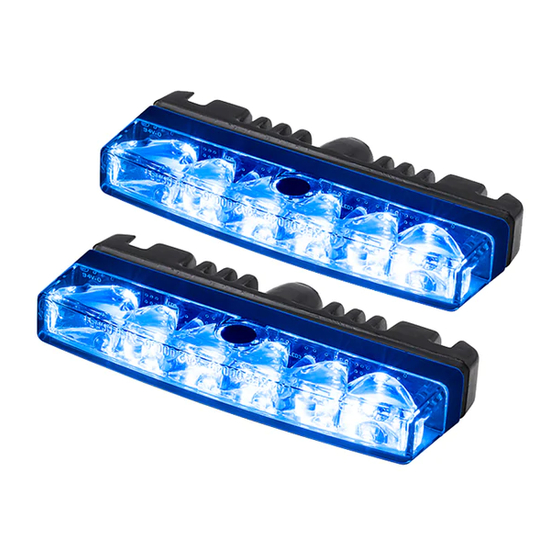
L54 Single Blue, Amber ECE R65 Class 2 / L54 Red ECE R65 Class 1
VERSIONS
45457021, L54 Single Blue
45487021, L54 Single Amber
45467021, L54 Single Red
E
E
5
XB2 00 049
5
XA2 00 050
45477021, L54 Single White
E
5
10 R - 05 250
WARNING! This product contains high intensity LED devices. To prevent eye damage, DO NOT
LOOK into the light beam at close range. NB! The cooling flange could become hot.
CONFIGURATION
For configurations of the Sync-mode and Flash Pattern follow further instructions.
NB! If STEP 2 and STEP 3 is performed incorrect one will have to restart from STEP 1.
1
Connect the POWER SUPPLY.
2
Wait at least 1 second & at most 6 seconds.
3
Connect the WHITE wire to ground (chassi) during at least 2 seconds.
4
Once in the configuration mode, a flash sequence will start, which
indicates the setting selected. To change the settings, follow the
instructions shown below Sync-mode & Flash Pattern.
5
Exit the configuration mode by cutting the POWER SUPPLY.
Reset to Factory Settings (default)
While in the configuration mode, connect the BLUE and the WHITE wire to ground
(chassi) during at least 2 seconds.
The reset is confirmed with a bright steady light for approximately 2-3 seconds.
Connections configuration
BLACK
RED
WHITE
BLUE
Synk-mode & Flash Pattern
In the configuration mode you can adjust and set the desired settings for sync-
mode and flash pattern. The settings are indicated by a series of flash sequences.
Count the number of flashes to find out the chosen settings (see table 2).
Sync-mode
For desired Sync-mode, connect the BLUE wire to ground (chassi).
Flash Pattern
For desired Flash Pattern, connect the
WHITE wire to ground (chassi).
NB! Each time the selected wire is connected to ground the
next version of SYNC-MODE or FLASH PATTERN is activated.
If the wire is kept connceted to ground a flash sequence
indicating the selected settings is shown, where Bright flashes
indicates the settings of Sync-mode and "Blank" flashes indicates
the selected Flash Pattern.
Sync-mode #1
Sync-mode #1 & Flash Pattern #1
Flash Pattern #1
Table 2 Selectable Functions
VERSION
FLASH
#1
x1
#2
x2
#3
x3
#4
x4
STANDBY AB
Nohabgatan 12C
Sweden
SE-461 53 Trollhättan
APPROVALS
E
XB2 00 049
5
E
E
E
E
5
XB2 00 049
5
XB2 00 049
5
XA2 00 050
5
XA2 00 050
E
E
5
XR1 00 051
5
10 R - 05 250
E
E
5
10 R - 05 250
5
10 R - 05 250
To Chassis Ground
To +10-30VDC
Activate configuration mode, choose Flash Pattern
Choose sync-mode
Bright Flash
Soft Light
Blank Flash
Sync-mode #2 & Flash Pattern #1
Sync-mode #4 & Flash Pattern #3
SYNC-MODE
FLASH PATTERN
Simultaneous
Double (default)
(default)
Alternate
Triple
Simultaneous
STEADY BURN 1
Alternate
STEADY BURN 2
website
E-mail
www.standby.eu
info@standby.eu
EN
Technical Data
Lens
House
Color
Diodes
Cable
Mounting
Synchronizing
Power
Ambient temp.
Size
E
E
Approvals
XA2 00 050
XR1 00 051
5
5
E
E
5
XR1 00 051
5
XR1 00 051
Included
MOUNTING
1
1
Connections mounting
Power
Supply
NB! The lamps electronic unit should be assembled in a weather protected area.
High pressure cleaning should not be used on a distance smaller than 40 cm. No grease,
oil or any foreign substances should be applied on the LED lamps gray/black membrane
or damaged mechanically.
Connections
Connect the POWER SUPPLY according to the following instructions.
1
Connect the BLACK wire to a good and suitable ground
2
Connect the RED wire to +10-30VDC via a 5A fuse
BUILT IN FLASH
The RED wire triggers the
lamp. Connect this wire to a
source output in an I/O-unit or
via a switch.
The WHITE wire is to sync
the lamp with other lamps.
Connect this wire with other
sync wires.
The BLUE wire controls the
day/night function. By con-
necting this wire to a sinking
output in an I/O-unit or via a
switch to ground, the lamp
Examples
will dim down to night level.
Telephone
+46 520 49 44 40
Polycarbonate
Aluminum (Black)
Blue, Amber, Red, White
6x High Power LED
0,84m (160mm+680mm)
+ 2,0m driver
Surface mount
Max 10x lamps
10-30 VDC
-40 - +85C
Lamp 85x36x15 mm
Driver 80x14,3x18,6 mm
Light: ECE R65 (E5), EMC: ECE R65 (E5)
1x Lamp L54, 1x Driver D13s
For mounting follow further instructions.
2
2
BLACK
To Chassis Ground
RED
To +10-30VDC
WHITE
BLUE
STEADY BURN 1
The WHITE wire triggers the
lamp. Connect this wire to a
sinking output in an I/O-unit
or via an external flasher for a
self-defined flash pattern.
* Steady Burn is used when an external flasher or
a control system is used to flash the lamp.
Set to STEADY BURN 1 or STEADY BURN 2 by
following further instructions shown below
Configuration.
Designed in Sweden
Copyright 2016 Standby AB. All rights reserved
Bracket Mount
(sold separately)
Power
Supply
see Table Connections
STEADY BURN 2
Follows the power supply.
Connect the RED wire to a
source output in an I/O-unit
of via an external flasher for a
self-defined flash pattern.
AM454sB
Advertisement

Related Manuals for Standby L54


Summary of Contents for Standby L54
- Page 1 USER MANUAL Ambient temp. -40 - +85C Size Lamp 85x36x15 mm L54 Single Blue, Amber ECE R65 Class 2 / L54 Red ECE R65 Class 1 Driver 80x14,3x18,6 mm VERSIONS APPROVALS Approvals Light: ECE R65 (E5), EMC: ECE R65 (E5)
- Page 2 10-30 VDC ANVÄNDARMANUAL Drifttemperatur -40 - +85C Mått Lampa 85x36x15 mm L54 Singel Blå, Gul ECE R65 Klass 2 / L54 Röd ECE R65 Klass 1 Driver 80x14,3x18,6 mm MODELLER TYPGODKÄNNANDE Typgodkännande Lampa: ECE R65 (E5), EMC: ECE R65 (E5)
- Page 3 +10-30 VDC MONTAGEANLEITUNG Betriebstemperatur -40 - +85°C Abmessung en Blitzmodul 85x36x15 mm L54 Single Blau, Gelb ECE R65 Klasse 2 / L54 Rot ECE R65 Klasse 1 Treiber 80x14,3x18,6 mm MODELLE ZULASSUNGEN Zulassungen Blitzmodul: ECE R65 (E5), EMV: ECE R10(E5)
- Page 4 MANUEL UTILISATEUR Température d’utilisation -40 - +85C Dimensions Feu 85x36x15 mm L54 Solo Bleu, orange eCe R65 Classe 2 / L54 Rouge eCe R65 Classe 1 Faisceau 80x14,3x18,6 mm VeRSIonS HoMoLogatIonS Homologations FEU: ECE R65 (E5), CEM: ECE R65 (E5)
Need help?
Do you have a question about the L54 and is the answer not in the manual?
Questions and answers