
Related Manuals for CONTRASTECH Mars Series


Summary of Contents for CONTRASTECH Mars Series
- Page 1 Mars Line Scan GigE Camera User Manual Using iCentral with Mars Line Scan GigE Cameras...
- Page 2 © 2016 Hangzhou ContrasTech Hangzhou ContrasTech reserves the right to make changes to this information without notice. Reproduction of this manual in whole or in part, by any means, is prohibited without prior permission having been obtained from Hangzhou ContrasTech.
-
Page 3: Table Of Contents
Contents 1 Product Description......................- 4 - 1.1 Product Introduction....................- 4 - 1.2 Product Features......................- 4 - 1.3 Product Construction....................- 4 - 1.3.1 Dimension......................- 4 - 1.3.2 Interface Description..................- 5 - 1.4 Indicator Description....................- 6 - 2 Camera Installation....................... - 7 - 3 iCentral Installation.......................- 7 - 4 iCentral Panes Description....................- 10 - 4.1 Tool Bar........................ -
Page 4: Product Description
1 Product Description 1.1 Product Introduction Mars Series Gigabit Ethernet Industrial Line Scan Camera, with high performance sensitive sensor, transmit image data through GigE data interface. It is compatible to any application development tools which follow the GigE Vision and GenICam Standard. -
Page 5: Interface Description
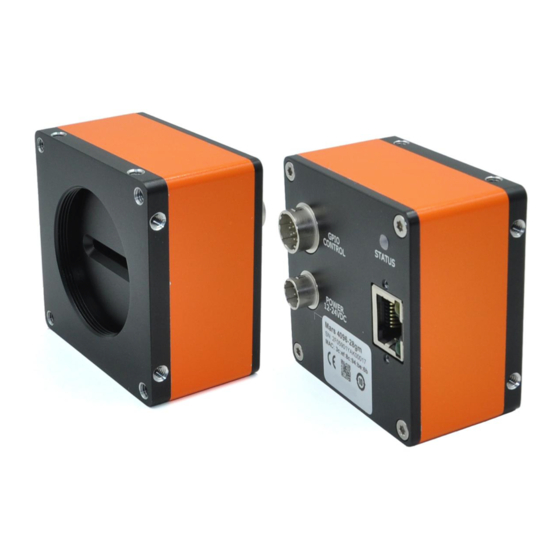
1.3.2 Interface Description The description of each interface as shown in Figure 1-2. Figure 1-2 Interface Description - 5 -... -
Page 6: Indicator Description
Description Power +12~24V DC Power No connection DC Power GND 1.4 Indicator Description Indicator Description of Mars Series Industrial Line Scan Cameras as shown in Table 1-1. Table 1-1 Indicator Description Status Mode Description Fast Flashing Red The device is starting. -
Page 7: Camera Installation
Open the camera box and take out the camera and accessories. Connect the camera to the power supply and make sure it is energized. After connecting the camera to the computer by Gigabit Ethernet cable, please download the SDK for the camera from Hangzhou ContrasTech website: wwww.contrastech.com... - Page 8 Note: Please check the following item. - 8 -...
- Page 9 3. Click the“iCentral.exe”icon to start the program 4. Once the iCentral started, the camera can be discovered in the same network segment and it will be displayed in ‘Device List’. Moreover, if there is a new camera in the network, it is required to click ‘refresh’...
-
Page 10: Icentral Panes Description
4 iCentral Panes Description The various areas of the iCentral are described in the figure below. Tool bar Acquisition Display Parameters Pane Message Window Control Buttons Acquisition Information 4.1 Tool Bar File: For user configuration. User can do the following operations: open, open recent, save and save - 10 -... -
Page 11: Visibility
Event Monitor:Show the camera stream Image: for saving images Configure: Please follow the instruction to change data. 4.2 Visibility All camera features have a Visibility attribute which defines its requirement or complexity. The states vary from Beginner (features required for basic operation of the device) to Guru (optional features required only for complex operations). -
Page 12: Parameters Pane
(Note: The number of parameters shown is dependent on different states. And the following description are mainly based on Guru state.) 4.3 Parameters Pane Parameters pane allows viewing or changing all acquisition parameters supported by the acquisition device. Parameters in gray are read only, either always or due to another feature being disabled. - Page 13 The following table describes each image format control features. Display Name Feature&Values Description SensorWidth SensorWidth Effective width of the sensor in pixels. SensorHeight SensorHeight Effective width of the sensor in pixels. WidthMax WidthMax Maximum width of the image (in pixels). The dimension is calculated after horizontal binning, decimation or any other function changing the horizontal dimension of the image.
- Page 14 4.3.3 AcquisitionControl The following table describes each Acquisition Control features. Display Name Feature&Values Description AcquisitionMode AcquisitionMode Sets the acquisition mode of the device. It defines mainly the number of frames to capture during an acquisition and the way the acquisition stops. Continuous Frames are captured continuously with AcquisitionStart until stopped with the...
- Page 15 AcquisitionStart AcquisitionStart Starts the Acquisition of the device. The number of frames captured is specified by AcquisitionMode. AcquisitionStop AcquisitionStop Stops the Acquisition of the device at the end of the current Frame. It is mainly used when AcquisitionMode is Continuous but can be used in any acquisition mode.
- Page 16 FallingEdge The trigger is considered valid on the falling edge TriggerDelay TriggerDelay Specifies the delay in microseconds (us) to apply after the trigger reception before activating it. TriggerMultiplier TriggerMultiplier Specifies a multiplication factor for the incoming trigger pulses. ExposureMode ExposureMode Sets the operation mode for the camera’s exposure.
-
Page 17: Digitaliocontrol
Line1_in- RS422 input- Line1_in+ RS422 input+/Single ended input Line3_in/out- RS422 I/O- Line3_in/out+ RS422 I/O+ / Single ended I/O Signal ground Signal GND Line5_out- RS422 output- Line5_out+ RS422 output+/ Single ended output Line2_in- RS422 input- Line2_in+ RS422 input+/ Single ended input Line4_GPIO Single ended I/O Line6_out-... -
Page 18: Eventcontrol
LineFormat LineFormat Controls the current electrical format of the selected SingleEnded/RS422 physical input or output Line. User Output Selector User Output Selector Selects which bit of the User Output register will be set by UserOutputValue. UserOutputValue UserOutputValue Sets the value of the bit selected by False/True UserOutputSelector. -
Page 19: Lutcontrol
Display Name Feature&Values Description Gain Selector Gain Selector Selects which Gain is controlled by the various Gain features. Gain Raw Gain Raw Controls the selected gain as an absolute Min: 0 physical value. This is an amplification factor Max: 6 applied to the video signal. - Page 20 The following table describes these parameters. Display Name Feature&Values Description PayloadSize PayloadSize Provides the number of bytes transferred for each image or chunk on the stream channel. This includes any end-of-line, end-of-frame statistics or other stamp data. This is the total size of data payload for a data block.
- Page 21 GEVCurrentIPConfigurationPers GEVCurrentIPConfigurationPers Controls whether istentIP istentIP PersistentIP configuration scheme is activated on the given logical link. GEVCurrentIPAddress GEVCurrentIPAddress Reports the IP address for the given locical link. GevCurrentSubnetMask GevCurrentSubnetMask Reports the subnet mask of the given logical link. GevCurrentDefaultGateway GevCurrentDefaultGateway Reports the default gateway IP address to be used on the given logical link.
- Page 22 unsuccessful retrieve device description file using the first URL. GevNumberOfInterfaces GevNumberOfInterfaces Indicates the number of logical links supported by this device. GevPersistentIPAddress GevPersistentIPAddress Controls Persistent address for this logical link. It is only used when the device boots with Persistent configuration scheme.
- Page 23 ExclusiveAccess Grants exclusive access to the device to an application. No other application can control or monitor the device. ControlAccess Grants control access to the device to an application. No other application can control the device. GevMCPHostPort GevMCPHostPort Controls the port to which the device must send messages.
-
Page 24: Usersetcont
maximum packet size supported by a GVSP receiver. GevSCPD GevSCPD Controls the delay (in timestamp counter unit) to insert between each packet for this stream channel. This can be used as a crude flow-control mechanism if the application or the network infrastructure cannot keep up with the packets coming from the device. -
Page 25: Counterandtimercontrol
UserSetSelector UserSetSelector Selects the feature User Set to load, save or configure. UserSetLoad UserSetLoad Loads User specified UserSetSelector to the device and makes it active. UserSetSave UserSetSave Save User specified UserSetSelector to the non-volatile memory of the device. UserSetDefault UserSetDefault Selects the feature User Set to load and make active by default when the device is reset. -
Page 26: Ispcontrol
TimerTriggerActivation TimerTriggerActivation Selects the activation mode of the trigger to RisingEdge/FallingEdge/ start the Timer. AnyEdge TimerDelay TimerDelay It sets the duration in device-specific unit of the Min: 1 delay to apply after the reception of a trigger Max: 65535 before to start the Timer. TimerDuration TimerDuration It sets the duration in device-specific unit of the... - Page 27 Hangzhou Contrstech Co.,Ltd Add.: No.11, Xiyuan 8th Road West Lake District, Hangzhou 310030 China TEL: 86-571-89712238 Fax: 400-8266-163*01460 Web site: www.contrastech.com E-mail: market@contrastech.com - 27 -...
Need help?
Do you have a question about the Mars Series and is the answer not in the manual?
Questions and answers