
Related Manuals for FW Murphy TDXM-DC Series

Summary of Contents for FW Murphy TDXM-DC Series
- Page 1 Temperature Scanner/Pyrometer Model TDXM-DC Installation and Operations Manual 00-02-0511 2019-07-10 Section 10...
- Page 2 BEFORE BEGINNING INSTALLATION OF THIS FW MURPHY PRODUCT: Read and follow all installation instructions. Please contact FW Murphy immediately if you have any questions. A visual inspection of this product for damage during shipping is recommended before installation.
-
Page 3: Table Of Contents
Table of Contents General Information ........................1 Description ........................1 User Interface .......................1 Thermocouple Types ....................1 Control Options ......................1 Setpoint History ......................1 Sensor Inputs and Terminals ..................1 RS485 Serial Port ......................1 Modbus Integer Holding Registers ................1 Replacement Parts .......................1 TDXM-DC Mounting ........................2 Dimensions ........................2 TDXM-DC Typical Wiring Diagram ................... - Page 4 (THIS PAGE INTENTIONALLY LEFT BLANK)
-
Page 5: General Information
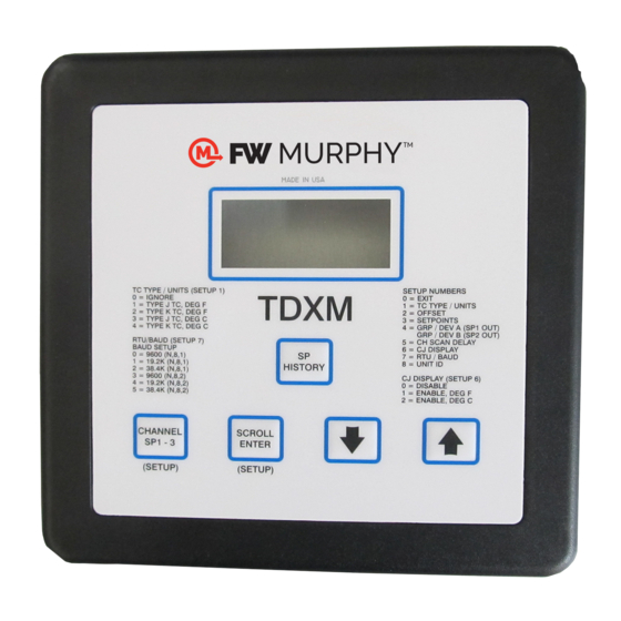
General Information Description The innovative TDXM-DC gives you a unique, configurable temperature scanner/pyrometer with a built-in power supply. The design features a 7-character, 7-segment Liquid Crystal Display window with 1/2 inch (13 mm) easy- to-read characters. Also located on the faceplate are membrane keys for easy configuring. Highly reliable and versatile, the TDXM-DC accepts up to 24 type J or K grounded or ungrounded* thermocouples. -
Page 6: Tdxm-Dc Mounting
TDXM-DC Mounting Warning: Turn the power source off before mounting the TDXM-DC. The TDXM-DC Series module was designed to be mounted within a weatherproof enclosure and is intended for mounting in a flat panel. 1. Precut a square mounting hole of 5.5 in. (140 mm) and four mounting holes 0.25 in. (6.35 mm) dia., see diagram. -
Page 7: Tdxm-Dc Typical Wiring Diagram
WARNING: Route the sensor input wires away from other wires (2 in. [51 mm] minimum). For hazardous application requirements, the TDXM-DC complete system must be installed in accordance with the national electrical code (NEC) Class I, Division 2, Groups C & D (article 504) specifications and per FW Murphy drawing number10-08-0006 Section 10 00-02-0511... -
Page 8: Tdxm-Dc I/O Addresses
TDXM-DC I/O Addresses Channel Eng. Units SetP#1 SetP#2 SetP#3 Offsets TC Type Ch#1 40,001 40,031 40,055 40,079 40,103 40,127 Ch#2 40,002 40,032 40,056 40,080 40,104 40,128 Ch#3 40,003 40,033 40,057 40,081 40,105 40,129 Ch#4 40,004 40,034 40,058 40,082 40,106 40,130 Ch#5 40,005 40,035... -
Page 9: Sequence Of Operations
Sequence of Operations Scanning Normal Scan the CHANNEL SP1-3 button again to return to the Normal or Locked Scan mode. No changes can be made to the set points During Normal Scan mode, each channel is displayed for the from this view. To change a set point, use the SETPOINTS (setup period set in the CH SCAN DELAY (Setup 5). -
Page 10: Setup
Setup To enter the SETUP routines, press the SCROLL ENTER and Setup 4 = GRP / DEV SETUP CHANNEL SP1-3 buttons simultaneously for 5 seconds. The Setup 5 = CH SCAN DELAY display will first show: Setup 6 = CJ DISPLAY SELECTION Setup 7 = RTU / BAUD SETUP Setup 1 TC TYPE / UNITS... - Page 11 Setup (continued)_________________________________________________ Use the UP and DOWN buttons to select the desired channel to cylinder engine, group will be set to 16. The first 16 channels will set up. (Select CH 0 to exit.) Press SCROLL ENTER, and the be in the group. The group can be all 24 channels. If a second group is used, it starts with the first channel after the first group.
- Page 12 Setup (continued)__________________________________________________ Use the UP and DOWN buttons to enter the desired Channel Scan This is the prefix for the unit number. It can be set from Ø (zero) to 99 Delay value (settable from 0 to 10 sec.). This is only for the display. using the UP and DOWN buttons.
-
Page 13: Map Of Setup
Map of Setup Section 10 00-02-0511 2019-07-10... - Page 14 Map of Setup (continued) Section 10 00-02-0511 2019-07-10...
-
Page 15: Deviation From Average
Deviation from Average TDXM-DC – Deviation from Average Calculations This example is for a 6-cylinder engine Figure 1 Figure 2 Deviation from Average TDXM-DC Enabling Channel Calculations Channels grPA= 6 Absolute (1 – ((2+3+4+5+6)/5)) Absolute (2 – ((1+3+4+5+6)/5)) Absolute (3 – ((1+2+4+5+6)/5)) Included Absolute (4 –... -
Page 16: Grouping Errors
Grouping Errors Because of the flexible nature of the TDXM-DC, the setup can cause conflicts when settings are made. If there is a conflict which will cause problems in the Group/deviation function, there will be error codes displayed. The display will show one of the values below: Group #1 Error 11 - Channel 1 disabled Error 12 - Too few channels... -
Page 17: Specifications
Specifications Power Input (Operating Voltages): 10–32 VDC, 4.2 W max Sensor Inputs: Up to 24 type J or K grounded or ungrounded thermocouples* Outputs: Two (2) Outputs 0.5 A, 350 VDC, FET-sink to ground to trip One (1) Form C Solid State Relay Output 0.125 A, 350 VDC/240 VAC NOTE: The form C relay output is de-energized for a trip condition. - Page 18 Notes Section 10 00-02-0511 2019-07-10...
- Page 19 Notes Section 10 00-02-0511 2019-07-10...
Need help?
Do you have a question about the TDXM-DC Series and is the answer not in the manual?
Questions and answers