Table of Contents
Advertisement
Quick Links
Advertisement
Table of Contents

Related Manuals for FUZRR ES1000 Series

Summary of Contents for FUZRR ES1000 Series
-
Page 2: Table Of Contents
CONTENT Ⅰ. Safety Precautions and Procedures………………………‥ 3 Ⅱ. Brief Introduction …………………………………………… 4 Ⅲ. Electrical Symbols …………………………………………… 5 Ⅳ. Technical Indicators ………………………………………… 6 Ⅴ. Outline Structure …………………………………………… 7 Ⅵ. H/L Voltage Clamp Meter Symbols ……………………… 8 1. Button Instructions …………………………………………… 9 2. - Page 3 5. Data Reference…………………………………………………16 6. Data Deletion……………………………………………………17 Ⅹ. Batteries ……………………………………………………… 17 Ⅺ. Accessories…………………………………………………… 17...
-
Page 4: Ⅰ. Safety Precautions And Procedures
Ⅰ. Safety rules and precautions Thank you for purchasing the company's high and low voltage clamp ammeter. To avoid possible electric shock or personal injury, please be sure to strictly observe the safety rules and precautions listed in this manual. ●... -
Page 5: Ⅱ. Brief Introduction
missing plastic parts. If the head and other parts of the instrument are damaged, please do not use it.. ● To avoid the impact of transducer clamp, it needs to maintain this meter regularly. Do not use corrosive or coarse materials to clean, but use soft cloth (such as glasses cloth), dip a lubricant that is rust-proof and dehumidified, and gently wipe the meter. -
Page 6: Ⅲ. Electrical Symbols
and high stability throughout the year.. The H/L Voltage Clamp Meter also has functions such as peak hold, data retention, data storage, wireless transmission, etc. Its special clamp ammeter can facilitate clamping or evacuation of the measured wire by pushing or retracting the insulation rod, saving time and fast. -
Page 7: Ⅳ. Technical Indicators
Ⅳ.Technical Indicators Range of Model Accuracy measurement Specification Φ50mm Base Model 0.0mA-1200A 0.1mA Φ50mm Wireless Model 0.0mA-1200A 0.1mA Insulation sheath wire test below 60kV line voltage, bare wire test below 60kV (with insulation rod operation) Jaw Specification: Φ50mm Range of measurement: 0.0mA-1200A(50/60Hz Auto Identification)... -
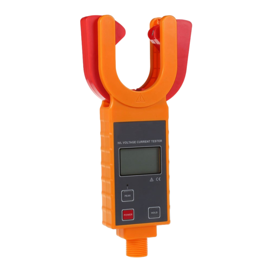
Page 8: Ⅴ. Outline Structure
Storage Temperature: -10℃~60℃ Relative Humidity: 0℃~31℃≦75%,31℃~40℃≦50% .Wireless Distance: 30m Insulating Rod: Five section insulation rods (5 meters in total) Insulation strength AC60kV/rms Parameter with symbol* is for the wireless model Ⅴ. Outline Structure Base Model Wireless Model Receiver for Wireless Model... -
Page 9: Ⅵ.h/L Voltage Clamp Meter Symbols
Description ① Clamp Jaw ② :LCD Display Base Type ③ PEAK Test Indication ④ PEAK Key ⑤ Insulation Rod Connector ⑥ POWER Key ⑦ Wireless Type Low Battery Indication ⑧ Wireless Type Power Indication ⑨ Wireless Type HOLD Key ⑩ Wireless Receiver LCD Display Insulation Rod(total 5m) Ⅵ.H/L Voltage Clamp Meter Symbols... - Page 10 Low battery voltage symbol, when the battery voltage is lower than 5.5V, this symbol shows, please replace the battery in time Data storage symbol Data access symbol Unit symbol Alternating current symbol HOLD Data retention Direct current symbol 3.Ordinary H/L Voltage Clamp Meter Test Display Instruction Status Symbol Instrucion The measured current exceeds the upper limit of...
-
Page 11: Ordinary H/L Voltage Clamp Meter Test Display Instruction
Lock the display data. This data is automatically stored as group 08. The measured current is: 100.6A The measured current is: 486A battery voltage low symbol display, please replace the battery in time Review the stored 08th set of the measured current, it’s data is: 100.6A Ⅶ.Basic H/L Voltage Clamp Meter Operating Instructions Please check all parts of the meter carefully... -
Page 12: Power On/Off
1. Power On/Off Press POWER button to power on, the instrument will displays the LCD screen, entering normal testing mode. If LCD display is relatively dark after power on, it is possible that battery voltage is a bit lower. Please replace battery. 15 minutes after powering on the meter, if it remains idle, an auto-power off procedure starts to preserve the battery life and LCD will continue flash until the complete switch off takes... - Page 13 current change. When the tester is removed away from the lead on test, it does not preserve the test result, LCD display will return to zero. In normal testing mode, it is suitable for close distance measurement, convenient for circuit test by direct read of LCD data.
-
Page 14: Peak Test
Press HOLD key to release the hand, LCD display HOLD symbol, enter HOLD mode, press HOLD key to exit measurement mode! Press and hold the HOLD button to release, enter the data query mode. In the data reference mode, press and hold the HOLD button to release the exit data reference mode and return to the normal test mode. -
Page 15: Data Reference
memory 100 groups of data, in case of full storage, “FULL” symbol will display by flash continuously, and it cannot continue to memory until cleaning out the previous memory. 6. Data Reference In the normal test mode, press and hold the HOLD button to release and enter the data reference mode. -
Page 16: Ⅸreceiver Operation
Data Clear, Clear Select "YFS", Do Not Clear Select "No"。 N O S I G N A L No signal received - - - - The measured current is 0.2mA Lock the display data, this data is automatically stored as group 06. The measured current is: 27.6A. -
Page 17: Data Reception
automatically shut down to reduce battery consumption. If the LCD continues to flash, press the POWER button to continue working. Under data reference, first, press POWER button( for 3 seconds ) to exit data reference mode, then come back to data receive mode, press POWER button once again to power off. - Page 18 the last group’s data in storage. Press HOLD button for more than 3 seconds to exit from data reference mode, returning to receiving data mode. Data Deletion Under any mode, press POWER button for more than 3 seconds, "Delete data?" appears, clear all stored data long press "YFS"...
- Page 19 The contents of this user manual cannot be used as a reason to use the product for special purposes. The company is not responsible for other losses caused by use. The company reserves the right to modify the contents of the user manual. If there is any change, it will not be notified.
Need help?
Do you have a question about the ES1000 Series and is the answer not in the manual?
Questions and answers