
Related Manuals for mfh systems E-NERGY CARBON Series

Summary of Contents for mfh systems E-NERGY CARBON Series
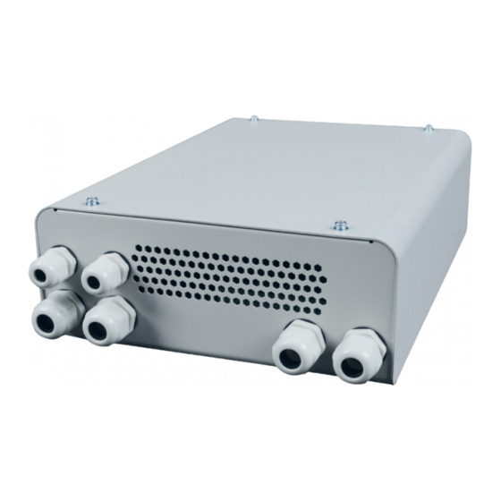
- Page 1 systems modern floor heating E-NERGY CARBON Electric surface heating system systems modern floor heating Installation instructions & operating manual Power supply unit BASIC TT...
-
Page 2: Installation Sketch
INSTALLATION SKETCH: Please keep this document in a safe place Heating foil Control unit Thermo sensor Transformer... -
Page 3: Table Of Contents
Installation instructions & operating manual E-NERGY CARBON Table of contents Installation sketch ......................02 Delivery condition ......................04 1.1. Scope of delivery ......................04 Information for users ..................... 04 2.1. Safety Instructions ......................04 2.2. General information ...................... 05 2.3. Function and application .................... -
Page 4: Delivery Condition
1. Delivery condition The E-NERGY CARBON panel heating system can be used as a full heating system, auxiliary heating or for surface tempering can be used in the renovation (e.g. mould prevention). 1.1 Scope of delivery • E-NERGY CARBON power supply unit BASIC TT •... -
Page 5: General Information
• Screw heads / washers must have a minimum diameter of 15 mm so that the fixing holes are sufficiently covered. • Protect the unit from moisture, heavy dust, aggressive liquids and vapours. • Always ensure sufficient heat dissipation (distance to thermal insulation) and ventilation. •... -
Page 6: Function And Application
The system is operated with safety extra-low voltage 36V and thus offers a maximum of electrical safety. The connection of the power supply unit to the house mains, as well as the installation of the temperature controller and the electrical connection of the heating foils may only be carried out by a qualified electrician. 2.3 Function and application The E-NERGY CARBON system is a foil heating system for walls, ceilings and floors that is optimised for radiant heat. -
Page 7: Installation
The E-NERGY CARBON heating foil is not designed for installation as a storage heating system and therefore cannot be used for installation within the floor screed. The closer the heating foil is installed to the surface of the room, the faster the heating system reacts and emits the pleasant heat radiation into the room. To facilitate your personal planning and documentation of the installation work, you should use the installation sketch (page 2). -
Page 8: Pretreatment Of The Substrate
plugs for electrical insulation. In addition, two screws must not be fitted with an electrically conductive material (e.g. metal picture frame, metal trim, metal shelving system). Do not use nails. 3.2.1. Pretreatment of the substrate The heating foil can be applied to any load-bearing, clean and level surface made of inorganic materials such as stone, screed, plaster, etc. -
Page 9: Installation Methods
Mindest-Wärmedurchgangskoeffizient und Mindest-Wärmeleitwider- Minimum heat transfer co stand der Bauteile. the components. Floor covering Heating foil Thin bed adhesive Screed Cover Insulation layer Thermal insulation and laying as direct heating in thin-bed adhesive. load-bearing floor 3.2.3 Installation methods Wärmedämmung und Verlegung als Direktheizung im Dünnbettkleber Heat insulation and install There are three different types of installation: (A) Embedding the film between inorganic layers with dispersion fillers or dispersion plaster systems such as... -
Page 10: Ceiling Installation
3.2.5. Ceiling installation When installing the E-NERGY CARBON heating foil in a suspended ceiling or if it is accessible from a roof space, a warning sign „Ceiling heating direct acting“ must be attached to the ceiling access opening. 3.2.6 Use in humid/wet rooms When used in humid/wet rooms, the requirements of DIN VDE 0100 Part 701 must be observed. -
Page 11: Overview Power Supply Of E-Nergy Carbon
4.1. Overview power supply of E-NERGY CARBON (see Figure 1) Input terminals primary side 230 V (L, N, PE) Output terminals secondary side 36 V Connection room thermostat 230 V (L, N, SK, N) heating circuit fuses, 15 A each Connection protective conductor for housing cover Figure 1 (Example power supply unit BASIC TT 800 W AP/UP) Switch contact N... -
Page 12: Installation Of Transformer
4.2. Installation of transformer The E-NERGY CARBON Power Supply BASIC TT is referred to as a device in the manual. The device may only be installed in closed rooms. It is designed for surface-mounted and Suitable for flush mounting and must be protected from moisture, heavy dust, aggressive liquids and vapors. Always ensure sufficient heat dissipation (distance to thermal insulation) and ventilation. -
Page 13: Connection Of Mains Voltage And Room Thermostat
4.3 Connection of mains voltage and room thermostat For connection to the supply voltage, the following specifications must be observed: Supply voltage 230 VAC, 50/60 Hz • The electric circuit for the connection must be sufficiently dimensioned and fused. When operating the heating system, this circuit must not be overloaded. •... - Page 14 Variant 2: Connection of a room thermostat to several Basic TT power supplies If several power supplies are controlled by one room thermostat, the room thermostat is connected to a power supply as described in Variant 1. In addition, the switching signal is connected in parallel to the switching contact SK and switching contact N of the other power supply units.
- Page 15 ema / Connection scheme Anschlussschema / Connection scheme 400W/800W/1200W AP/UP Basic TT 36-400W/800W/1200W AP/UP DC Filter( optional ) DC Filter( optional ) Netzanschluss/ Mains Supply 230V/50Hz 230V/50Hz Thermostat Last/ Load Heizkreis/Output S1 Heizkreis/Output S1 Heating circuit/Output S1 Heating circuit/Output S1 Heizkreis/Output S2 Heizkreis/Output S2 Heating circuit/Output S2 Heating circuit/Output S2 Heizkreis/Output S3 Heizkreis/Output S3 Heating circuit/Output S3 Heating circuit/Output S3...
-
Page 16: Heating Circuit Connection
Variant 3: Connection of a potential-free switching contact When using a potential-free switching contact, the supply terminal room thermostat L (230 V) is connected to the switching contact SK via the potential-free contact. In addition, the supply terminal room thermostat N must be Anschlussschema / Connection scheme connected to the switching contact N. -
Page 17: Electrical Commissioning
4.5 Electrical commissioning The electrical installation work on the device is now complete. Carefully check again that the installation work has been carried out. For commissioning, switch the supply circuit back on. After the circuit has been activated and if the installation is correct, the room thermostat will be activated. When the room thermostat gives the signal for heating, the unit switches on. -
Page 18: Technical Data
7. Technical data E-NERGY CARBON power supply unit BASIC TT 400 | 800 | 1200 W 400W | 800 W | 1200W Nominal power Nominal voltage primary 230 V AC 50/60 Hz Nominal voltage secondary 36 V AC (SELV, Safety Extra Low Voltage) Power supply 230 V (primary) Spring clamp terminals 1,5 mm²... - Page 19 110 W/m (hicoTHERM® 36-110) 110 W/m 15 A UP 220 W/m (hicoTHERM® 36-220) 220 W/m Schutzmaßnahme: FI-Schutzschaltung 3 Leistung pro Laufmeter: 35 W / lfm (hicoTHERM® 36-60) Output per metre: 35 W / m Nenngrenztemperatur: + 70 °C 65 W / lfm (hicoTHERM® 36-110) 65 W / m Mindestverarbeitungstemperatur: + 5 °C...
-
Page 20: Resistance Values As A Function Of Length
Per connection (output terminal pair 36 V) max. 400 W may be connected. The connected total power must not exceed the rated power of the power supply unit. E-NERGY CARBON FLEECE – 36 W/lfm (60 W/m²) max. 11 m E-NERGY CARBON FLEECE – 66 W/lfm (110 W/m²) max. - Page 21 8. Resistance values as a function of length* FLEECE FLEECE FLEECE FLEECE S FLEECE S Length 36 W/lfm 66 W/lfm 132 W/lfm 25 W/lfm 50 W/lfm 69 W/lfm (60 W/m²) (110 W/m²) (220 W/m²) (145 W/m²) (290 W/m²) (115 W/m²) 2,4 m 15,24 Ω...
- Page 22 8. Resistance values as a function of length* FLEECE FLEECE FLEECE FLEECE S FLEECE S Length 36 W/lfm 66 W/lfm 132 W/lfm 25 W/lfm 50 W/lfm 69 W/lfm (60 W/m²) (110 W/m²) (220 W/m²) (145 W/m²) (290 W/m²) (115 W/m²) 6,0 m 6,10 Ω...
- Page 23 8. Resistance values as a function of length* FLEECE FLEECE FLEECE FLEECE S FLEECE S Length 36 W/lfm 66 W/lfm 132 W/lfm 25 W/lfm 50 W/lfm 69 W/lfm (60 W/m²) (110 W/m²) (220 W/m²) (145 W/m²) (290 W/m²) (115 W/m²) 9,6 m 3,81 Ω...
-
Page 24: Warranty And Guarante
8. Resistance values as a function of length* FLEECE FLEECE FLEECE FLEECE S FLEECE S Length 36 W/lfm 66 W/lfm 132 W/lfm 25 W/lfm 50 W/lfm 69 W/lfm (60 W/m²) (110 W/m²) (220 W/m²) (145 W/m²) (290 W/m²) (115 W/m²) 13,2 m 3,91 Ω... - Page 25 The warranty service of mfh systems first of all includes a check whether a warranty claim exists. Should a warranty claim exist, mfh systems can determine the way in which the fault is to be remedied. mfh systems is at liberty to refund the proven invoice amount for the heating foil, to repair the E-NERGY CARBON surface heating foils itself, or to have them repaired by a third party and to bear the costs incurred.
- Page 27 Resistance values Room Lane no. Length Performance Resistance before mounting Resistance after mounting Ω Ω Ω Ω Ω Ω Ω Ω Ω Ω Ω Ω Ω Ω Ω Ω Ω Ω Ω Ω Ω Ω Ω Ω Ω Ω Ω Ω...
-
Page 28: Ec Declaration Of Conformity
10. EC declaration of conformity Products: E-NERGY CARBON Power supply BASIC TT 400 E-NERGY CARBON Power supply BASIC TT 800 E-NERGY CARBON Power supply BASIC TT 1200 E-NERGY CARBON FLEECE – 36 W/lfm (60 W/m²), E-NERGY CARBON FLEECE – 66 W/lfm (110 W/m²), E-NERGY CARBON FLEECE –... - Page 29 heating foil assembled, ..E-NERGY CARBON room thermostats including temperature sensor, ... and E-NERGY-CARBON power supply BASIC TT...
- Page 30 Notes...
- Page 32 LEAD FREE Im Einklang mit RoHS mfh systems GmbH Online download area Hager Feld 8 49191 Belm-Vehrte Germany Fon +49 (0) 54 06 | 699 95-10 Fax +49 (0) 54 06 | 699 95-90 Social Media mail@mfh-systems.com www.mfh-systems.com...
Need help?
Do you have a question about the E-NERGY CARBON Series and is the answer not in the manual?
Questions and answers