Advertisement
Table of Contents
- 1 Table of Contents
- 2 Safety Instructions
- 3 Components of the Proox 360
- 4 User Supplied Parts
- 5 Setup of Gas Supply
- 6 Proox 360 Front Panel Installation
- 7 Proox 360 Back Panel Installation
- 8 Operation
- 9 Program Functions Menu
- 10 Configuration
- 11 Calibration
- 12 Tuning
- 13 Single Setpoint Control
- 14 Setting the Alarm Setpoint
- 15 Maintenance
- 16 Warranty
- Download this manual
This manual is intended to help our customers efficiently
setup and operate the equipment. We encourage not only all
installers, but also all users, to read this manual thoroughly.
Keep it handy and refer to it often. Save it for future
reference. If you have any problems or questions, please do
not hesitate to call. We are here to help.
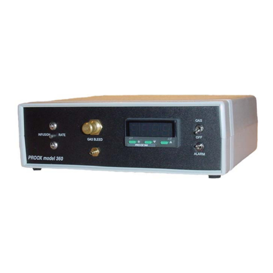
The Proox model 360 is a versatile and compact gas oxygen controller for people who
do oxygen sensitive work. Though designed to work with BioSpherix chambers the Proox
360 works in incubators, glove boxes, animal cages, refrigerators, plant growth chambers,
and many other semi-sealable chambers. Pratically any medium-large enclosure can be
fitted.
The unit works from
outside of the host cham-
ber by remotely sensing
and displacing air oxygen
inside the chamber with
another gas. Nitrogen or
an oxygen poor gas, is
used to lower the oxygen
level inside the host
chamber. Oxygen or an
6678 Route 17
Redfield, New York 13437
315-387-3414
FAX 315-387-3415
TOLL FREE US/CAN 800-441-3414
www.biospherix.com
Anyone who has not thoroughly read and under-
stood this manual, must never attempt to operate
!
Proox Model 360
Manual
version 1.0 June 2005
Introduction
oxygen enriched gas is used to raise the oxygen level
within the host chamber.
Nominal range is 0.1-99.9% oxygen. Advanced
feedback algorithms handle practically any oxygen gas
dynamic. Infusion rates are adjustable up to 350
SCFH. Installation is easy. Operation is simple. The
unit moves easily from one host chamber to another.
Please read and follow the safety and operations
instructions on the following pages. Be careful. Oxy-
gen can be dangerous. Any pressurized gas can be
dangerous. Know what you are doing and do it safely.
the equipment.
1
Proox model 360
version 1.0
!
Advertisement
Table of Contents

Related Manuals for BioSpherix Proox 360


Summary of Contents for BioSpherix Proox 360
- Page 1 The Proox model 360 is a versatile and compact gas oxygen controller for people who do oxygen sensitive work. Though designed to work with BioSpherix chambers the Proox 360 works in incubators, glove boxes, animal cages, refrigerators, plant growth chambers, and many other semi-sealable chambers.
-
Page 2: Table Of Contents
Table of Contents Proox model 360 version 1.0 Safety Instructions................3 Components of the Proox 360............4 User Supplied Parts...............5 Setup of Gas Supply..............6 Proox 360 Front Panel Installation..........7 Proox 360 Back Panel Installation..........8 Operation..................9 Program Functions Menu............10 Configuration................11 Calibration................12-14 Tuning..................15-18 Single Setpoint Control............19-20 Setting the Alarm Setpoint............21... -
Page 3: Safety Instructions
POWER CORD PROTECTION power supply cords should be routed so that they are not likely to be walked on or pinched by items placed upon or against them. ELECTRIC SHOCK do not remove cover of Proox 360 due to presence of uninsulated "dangerous voltage" within product's enclosure. -
Page 4: Components Of The Proox 360
Components of the Proox 360 Proox model 360 version 1.0 This section will familiarize you with the components that come with the Proox 360. Proox 360 unit 12VDC regulated power supply Calibration chamber with tubing Oxygen gas sensor Gas fitting Short piece of 1/8 in. -
Page 5: User Supplied Parts
User Supplied Parts Proox model 360 version 1.0 This section will describe any parts that you will need to provide, in or- der to properly operate the equipment. 1. Qty. 1 regulator, per compressed gas source, either a one stage regulator or a two staged regulator. -
Page 6: Setup Of Gas Supply
Proox 360. If the regulator is not near the Proox 360 then there should be a shutoff valve upstream of the Proox 360 so as to have the ability to control the gas flow. When taking off gas supply tube always make sure to shut off com- pressed gas at the source first, then bleed the pressure out of the line and then take off the tube from back of Proox 360. -
Page 7: Proox 360 Front Panel Installation
Proox 360 counterclockwise. If gas is heard expelling out the “GAS BLEED” barb on the front panel then the gas is connected properly. -
Page 8: Proox 360 Back Panel Installation
Plug the 12VDC regulated power sup- ply into a wall outlet. Then plug the jack end into the port labeled “12VDC” on back of the Proox 360. The display on the front of the Proox 360 should turn on. 2. Connecting Gas Attach 1/4 in. -
Page 9: Operation
Operation Proox model 360 version 1.0 This section will give an overview of some of the different modes and functions within the Proox 360. SINGLE LEVEL NAVIGATION Press up or down key once to move to the next function. Hold up or down keys to automatically index through the functions. -
Page 10: Program Functions Menu
Proox model 360 Program Functions Menu version 1.0 PROGRAM MODE FUNCTIONS MENU is arranged on 4 levels. Entry into menu is bottom of level 1. Exit menu from any point. Level 4 is hidden for security; there's one way in. Menu items are loosely grouped together according to similar functions. -
Page 11: Configuration
Configuration Proox model 360 version 1.0 Extensive configuration options in alarming, security, and display functions all can be set later, if necessary. Only one main configuration setting is required to start ... high or low oxygen SECONDARY CONFIGURATIONS SP1 control direct Alarm configuration options SP2 alarm reverse include deviation, band, and... -
Page 12: Calibration
Calibration Proox model 360 version 1.0 Calibration is the key to control accuracy. Check calibration at least once a week to have as much confidence as necessary in accuracy. SENSORS CALIBRATION CALIBRATION MENU The sensor drives the controller. Calibration electronically cor- FUNCTIONS If the sensor is not calibrated, it won't rects for the difference among sen-... - Page 13 "GAS SUPPLY 40 PSIG should be "0.0". MAX" on the back of the Proox 360. 7. Now to set the SPAN. Close Make sure the gas is regulated to 5- the bleed valve knob then remove the 40 PSIG.
- Page 14 "GAS SUPPLY thoroughly equilibrate to tempera- 40 PSIG MAX" on the back of the ture of surroundings. Proox 360. Make sure the gas is Temperature effect places a regulated to 0-40 PSIG. Never ex- time limit on calibration procedure. A ceed 40 PSIG.
-
Page 15: Tuning
Tuning Proox model 360 version 1.0 Tuning matches control parameters of Proox 360 to gas dynamics of host chamber to achieve effective control. TUNING right, it may never need further at- tuned, however, any change in the tention. power/load balance may require re- Different oxygen control jobs in tuning those parameters. - Page 16 On/off tuning has no provision less pulsing long before oxygen gets for fluctuating loads. Blindly responds even close to setpoint. Proox model 360 only to on-to-off point and off-to-on Cycle time should be as long version 1.0 point. Change in load may change as possible to minimize wear and oscillation amplitude and/or period.
- Page 17 ally oscillation will dampen to steady denly pulls away from setpoint. Prop- state, if load hasn't changed yet. erly tuned, derivative should not dis- Proox model 360 If integral time is too long, it's turb proportional or integral action at version 1.0 slow to respond.
- Page 18 (20.8), starts on approach to setpoint. Nor- Proox 360 can calculate it's own mally derivative action is only in pro- control parameters. It runs a few portional band. "dAC" is a multiplier tests on host chamber.
-
Page 19: Single Setpoint Control
1. Make sure the compressed nitrogen gas supply is connected to the back panel of the Proox 360 at the “GAS SUPPLY 40 PSIG MAX” barb. Make sure that the infusion tube is connected to the Proox 360 and the other end is connected to the chamber. - Page 20 Single Setpoint Control cont. Proox model 360 version 1.0 4. To set a setpoint, push and hold the “*” button. While holding the “*” button use the “up” and “down” buttons to adjust the “set” to read what you want the setpoint to be. Once you have adjusted the number to the desired reading, release the “*”...
-
Page 21: Setting The Alarm Setpoint
Setting the Alarm Setpoint Proox model 360 version 1.0 This section will explain how to set the alarm setpoint. Remember, when you wish the alarm function to be active you must make sure the alarm switch on the front of the controller is on. 1. -
Page 22: Maintenance
On average the sensor will last 1-2 years. New Sensor In the event that the sensor quits functioning call the number on the side of the sensor to purchase a new one. To replace the sensor follow step “4” of “Proox 360 Back Panel Installation”. -
Page 23: Warranty
This warranty does not cover sensors. GENERAL CONDITIONS OF WARRANTY This warranty shall be void if apparatus, in the judgement of BioSpherix, has been subject to mis-use, negligence, chemical action, accident or operated contrary to those operating procedures recommended by BioSpherix, or if the serial number and/or trade- marks have been altered, defaced or removed.
Need help?
Do you have a question about the Proox 360 and is the answer not in the manual?
Questions and answers