Table of Contents
Advertisement
Quick Links
Cable And Pipe Signal Receiver
Part 17-300R
C
a
P
S
able
nd
iPe
ignal
Part 17-300RTK
C
a
P
S
able
nd
iPe
ignal
W
t
ith
RanSmitteR
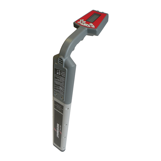
Jameson's 17-300R Cabel and Pipe Signal Receiver has an ergonomic design for one-hand operation and highly vis-
ible display. Works with transmitter to detect active frequencies, adjusting to work at different sites and applications.
Locate any continuous metal run - iron, steel and copper water lines, gas lines, tracer wire by plastic pipe, telephone/TV
cables, copper and aluminum wire, conduit, power lines and Duct Hunter™ Traceable Rodders.
4 Frequencies: 512 Hz, 8 KHz, 33KHz and 82 KHz.
R
eCeiveR
R
eCeiveR
OPERATION AND SAFETY
INSTRUCTION MANUAL
General Information
Part 17-500T
t
RanSmitteR
Advertisement
Table of Contents

Related Manuals for Jameson 17-300R


Summary of Contents for Jameson 17-300R
- Page 1 RanSmitteR General Information Jameson’s 17-300R Cabel and Pipe Signal Receiver has an ergonomic design for one-hand operation and highly vis- ible display. Works with transmitter to detect active frequencies, adjusting to work at different sites and applications. Locate any continuous metal run - iron, steel and copper water lines, gas lines, tracer wire by plastic pipe, telephone/TV cables, copper and aluminum wire, conduit, power lines and Duct Hunter™...
-
Page 2: Table Of Contents
Failure to observe these warnings could result in severe injury, death or property damage. Disclaimer Of Liability Jameson shall not be liable to distributor, reseller or any other person for any incidental, indirect, special, exemplary or consequential damages, or injury of any type whatsoever and caused directly or indirectly by products sold or supplied by Jameson. -
Page 3: Prepare For Use
Prepare For Use Unpack Locator and make sure there is no shipping damage and all the parts are included. Locate battery compartment on back of the “head” of Receiver. Open compartment using a phillips screwdriver. Install six “C” batteries as marked. Transmitter (“TX”) Controls and Indicators Load Rate Indicators... -
Page 4: Direct Connection
DO NOT CONNECT TO LIVE OR CAUTION ENERGIZED POWER CABLES Direct Connection Direct Connection is the most reliable method of signal application. This method is relatively free of interference. The greatest amount of signal strength can be achieved by this method. Low, mid and high frequency may be used. -
Page 5: Selecting Tracing Signal
The locating range is quite short for the 82 kHz signal so Transmitter must be repositioned more often during tracing operation. Also useful for applying a signal to the Jameson Duct Hunter™. -
Page 6: Receiver Controls And Indicators
Receiver Controls and Indicators Displays Absolute Signal Operation Mode Displays Selected Operation Strength or Depth Available to Model Measures Depth (+Shift Key Measures Current) Relative Signal Strength Bargraph (Single Bar Shows Gain Setting) On/Off Button Displays Selected Frequency Frequency Selector (+Shift Key Toggles Mode Selector On/Off Backlight) -
Page 7: Locating The Cable Or Pipe
Locating Cable or Pipe Make sure Transmitter is connected and in the ON position. Move approximately 15 feet (4.5 meters) away from Transmitter along the path. (Move about 25 feet (7.5 meters) for Inductive search mode.) Hold Receiver so you can see LCD bargraph and controls easily. Make sure Receiver and Transmitter frequency are set for the same frequency, either 512 Hz (lower), 8 kHz, 33kHz or 82 kHz (higher). -
Page 8: Null Locating Mode
Null Mode Locating Move Receiver left to right across cable path. When Receiver is directly above cable or pipe, a Null (lowest meter reading and lowest audio tone) will occur. When moving Receiver left or right of Null point, meter reading will rise to a maximum point (Peak). The audio tone will also be at its highest pitch. -
Page 9: Push Button Depth
Receiver also may be detecting adjacent cables or is not directly over target conductor. Verify target conductor path precisely before measuring current again. If at anytime the display reads ‘CAL’, contact Jameson. Current Measurement The Receiver contains a feature very useful in identifying a desired cable in a field of various conductors and/or utilities. -
Page 10: Tilted Magnetic Field Identification
Depth Measurement 45º Angle Method Move to a location where you want to measure depth. Stay at least 15 feet away from Transmitter. Move Receiver left to right across path until cable is located. Mark path on the ground as precisely as possible using the Null Method. -
Page 11: Specifications
Specifications Transmitter 82 kHz • 33kHz • 8 kHz • 512 Hz Operating Frequency -4°F to 133º (-20ºC to +55ºC) Operating Temperature Direct Connection Inductive Coupling (with optional coupler) Hook-up Method Transmitter Induction Ω Ω Load Matching Automatic from 5 to 20,000 1 Watt (High) 500 Milliwatts (Low) Output Power... - Page 12 800.346.1956 WWW.JAMESONLLC.COM Loc_17300R__MO3...
Need help?
Do you have a question about the 17-300R and is the answer not in the manual?
Questions and answers