Table of Contents
Advertisement
Quick Links
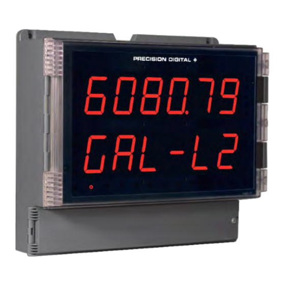
Helios Large Display Modbus
Instruction Manual
• Large 1.80" Digits
• Dual-Line 6-Digit Display
• Readable from up to 100 Feet (30 Meters) Away
• Superluminous Sunlight Readable Display
• NEMA 4X, IP65 Rated Field Mountable Enclosure
• Operating Temperature Range of -40 to 65°C (-40 to 150°F)
• Modbus® RTU Master, Slave, or Snooper Mode
• Poll and Display up to 16 Process Variables
• Addition, Difference, Average, Multiplication, Division, Min,
Max, Weighted Average, Ratio, Concentration, & More
• Input Power Options Include 85-265 VAC or 12-24 VDC
• 2 or 4 Relays + Isolated 4-20 mA Output Options
• Onboard USB & RS-485 Serial Communication Options
• Program the Meter from a PC with onboard USB and ScanView
PRECISION DIGITAL CORPORATION
233 South Street • Hopkinton MA 01748 USA
Tel (800) 343-1001 • Fax (508) 655-8990
®
Scanner
PD2-6080/1
Modbus Scanner
www.predig.com
Advertisement
Table of Contents

Subscribe to Our Youtube Channel
Related Manuals for Precision Digital Corporation Helios PD2-6080/1


Summary of Contents for Precision Digital Corporation Helios PD2-6080/1
- Page 1 • 2 or 4 Relays + Isolated 4-20 mA Output Options • Onboard USB & RS-485 Serial Communication Options • Program the Meter from a PC with onboard USB and ScanView PRECISION DIGITAL CORPORATION 233 South Street • Hopkinton MA 01748 USA Tel (800) 343-1001 • Fax (508) 655-8990...
- Page 2 Limited Warranty Precision Digital Corporation warrants this product against defects in material or workmanship for the specified period under “Specifications” from the date of shipment from the factory. Precision Digital’s liability under this limited warranty shall not exceed the purchase value, repair, or replacement of the defective unit.
-
Page 3: Table Of Contents
PD2-6080/1 Helios Large Display Modbus ® Scanner Instruction Manual Table of Contents Table of Contents ............ 3 Slave Mode (Slave) ........34 Table of Figures ............4 Setting up the Scanner (setup) ......35 Introduction.............. 5 Setting up the Process Variables (PVs) (pv Ordering Information .......... -
Page 4: Table Of Figures
Helios Large Display Modbus ® Scanner Instruction Manual PD2-6080/1 Protecting or Locking the Meter .....54 Low-Flow Cutoff (CutofF) ......68 Making Changes to a Password Protected Analog Output Programming (AoutPr) ..69 Meter ..............54 User Menu (user) .......... 70 Disabling Password Protection ......54 Digital Input Menu (dI 1) ........ -
Page 5: Introduction
A fully loaded Helios PD2-6080/1 meter comes with four (4) SPDT relays, a 4 20 mA output, two 24 VDC power supplies, five (5) digital inputs and four (4) digital outputs, and RS485 serial communications. Free ScanView software allows the Helios Modbus Scanner to be accessed via computer. -
Page 6: Specifications
Helios Large Display Modbus ® Scanner Instruction Manual PD2-6080/1 Specifications Except where noted all specifications apply to operation at +25°C. Slave 0.0 to 99.9 seconds: Time allowed for Operating Modes Response the slave to respond before the Master Processes data read from Modbus Timeout scanner generates a communication RTU slave devices. -
Page 7: Display Settings
PD2-6080/1 Helios Large Display Modbus ® Scanner Instruction Manual Display Settings Serial Communications Scan Mode Automatic: 1.0 to 99.9 sec Compatibility EIA-485 Manual: Front panel or digital inputs Connectors Removable screw terminal Go on alarm: Continues scanning connector after an alarm is detected Max Distance 3,937' (1,200 m) max Stop on alarm: Goes to the alarmed... -
Page 8: Relays
Helios Large Display Modbus ® Scanner Instruction Manual PD2-6080/1 Relays Power Options 85-265 VAC 50/60 Hz, 90-265 VDC, 20 W max or 12-24 VDC 10%, 15 Rating 4 SPDT (Form C) internal rated 3 A W max @ 30 VDC and 125/250 VAC resistive load;... -
Page 9: Isolated 4-20 Ma Transmitter Output
PD2-6080/1 Helios Large Display Modbus ® Scanner Instruction Manual Isolated 4-20 mA Transmitter Output Signal Input Linear, square root, programmable exponent, or Conditioning Output Source Input channels A or B, rate, total, or round horizontal tank volume grand total; channel C; max or min for channel A or B;... -
Page 10: Compliance Information
Helios Large Display Modbus ® Scanner Instruction Manual PD2-6080/1 Compliance Information Safety UL & C-UL Listed USA & Canada UL 508 Industrial Control Equipment (United States), C22.2 No. 142 (Canadian National Standard) UL File Number E160849 Front Panel UL Type 4X, NEMA 4X, IP65 Low Voltage Directive EN 61010-1:2010 Safety requirements for measurement, control, and laboratory use... -
Page 11: Safety Information
PD2-6080/1 Helios Large Display Modbus ® Scanner Instruction Manual Safety Information Caution: Read complete instructions Warning: Risk of electric shock or personal injury. prior to installation and operation of the meter. Hazardous voltages exist within enclosure. Installation and service should be performed only by trained service personnel. -
Page 12: Wall Mounting Instructions
Helios Large Display Modbus ® Scanner Instruction Manual PD2-6080/1 Wall Mounting Instructions The meter can be mounted to any wall using the four provided mounting holes. Note that the bottom mounting holes are located underneath the front door panel. To mount the meter to a wall, follow these instructions. -
Page 13: Pipe Mounting Instructions
PD2-6080/1 Helios Large Display Modbus ® Scanner Instruction Manual Pipe Mounting Instructions The meter can also be mounted to a pipe using the optional pipe mounting kit (PDA6260). This kit includes two mounting plates, two U-bolts, and the necessary nuts and bolts. To mount the meter to a pipe using the pipe mounting kit accessory, follow these instructions. -
Page 14: Transmitter Supply Voltage Selection (P+, P-)
Helios Large Display Modbus ® Scanner Instruction Manual PD2-6080/1 Transmitter Supply Voltage Selection (P+, P-) All meters, including models equipped with the 12-24 VDC power option, are shipped from the factory configured to provide 24 VDC power for the transmitter or sensor. If the transmitter requires 5 or 10 VDC excitation, the switch labeled P+/P- must be configured accordingly. -
Page 15: Connectors Labeling
PD2-6080/1 Helios Large Display Modbus ® Scanner Instruction Manual Connectors Labeling The connectors’ label, affixed to the inside of the lower door panel, shows the location of all connectors available with requested configuration. Do not connect any equipment other than Precision Digital’s expansion modules, cables, or meters to the RJ45 M-LINK connector. -
Page 16: Serial Communications Connection
Helios Large Display Modbus ® Scanner Instruction Manual PD2-6080/1 Serial Communications Connection An RS-485 connector is provided for the use of Modbus serial ® communications. This connector is used to interface the Modbus scanner with other Modbus devices. It has a removable screw terminal connector for the RS-485 terminals which includes Transmit Data (DO) and (/DO), Receive Data (DI) and (/DI), and Signal Ground. -
Page 17: Figure 11. Rs-485 Two-Wire Multi-Drop Wiring
PD2-6080/1 Helios Large Display Modbus ® Scanner Instruction Manual Figure 11. RS-485 Two-Wire Multi-Drop Wiring Notes: 1. Termination resistors are optional and values depend on the cable length and characteristic impedance. Consult the cable manufacturer for recommendations. 2. Refer to RS-232 to RS-485 Converter documentation for further details. 3. -
Page 18: Digital I/O Connections
Helios Large Display Modbus ® Scanner Instruction Manual PD2-6080/1 Digital I/O Connections Digital inputs and outputs are provides in order to expand the functionality of the meter. Digital inputs are made via a push button or switch connection to the appropriate digital input connector block and the +5 VDC block. -
Page 19: Relay Connections
PD2-6080/1 Helios Large Display Modbus ® Scanner Instruction Manual Relay Connections Relay connections are made to two six- terminal connectors labeled RELAY1 – RELAY4 on Figure 7. Each relay’s C terminal is common only to the normally RELAY1 RELAY2 RELAY3 RELAY4 open (NO) and normally closed (NC) contacts of the corresponding relay. -
Page 20: 4-20 Ma Output Connections
Helios Large Display Modbus ® Scanner Instruction Manual PD2-6080/1 4-20 mA Output Connections Connections for the 4-20 mA transmitter output are made to the connector terminals labeled MA OUT. The 4-20 mA output may be powered internally or from an external power supply. Figure 19. -
Page 21: Analog Input Signal Connections
PD2-6080/1 Helios Large Display Modbus ® Scanner Instruction Manual Analog Input Signal Connections Signal connections are made to a nine-terminal connector labeled SIGNAL on Figure 7. The COM (common) terminals are the return for the 4-20 mA and the 10 V input signals. The two COM terminals connect to the same common return and are not isolated. -
Page 22: Setup And Programming
Helios Large Display Modbus ® Scanner Instruction Manual PD2-6080/1 Setup and Programming The analog inputs of the scanner are factory calibrated prior to shipment to read in milliamps and volts, depending on the input selection. The calibration equipment is certified to NIST standards. Overview There are no jumpers to set for the meter input selection. -
Page 23: Programming Buttons And Status Led Indicators
PD2-6080/1 Helios Large Display Modbus ® Scanner Instruction Manual Programming Buttons and Status LED Indicators The meter can be programmed using the buttons located behind the front door panel. Use the Menu button to enter or exit Programming Mode, the Up Arrow button to cycle through menu options, and the Enter button to select the menu item or option you want. -
Page 24: Scanview Software
Helios Large Display Modbus ® Scanner Instruction Manual PD2-6080/1 ScanView Software The meter can also be programmed using the PC-based MeterView Pro software included with the meter. This software is can be installed on any Microsoft® Windows® (2000/XP/Vista/7/8/10) computer by connecting the meter’s onboard USB. -
Page 25: Display Functions & Messages
PD2-6080/1 Helios Large Display Modbus ® Scanner Instruction Manual Display Functions & Messages The meter displays various functions and messages during setup, programming, and operation. The following table shows the main menu functions and messages in the order they appear in the menu. Display Parameter Action/Setting Description... - Page 26 Helios Large Display Modbus ® Scanner Instruction Manual PD2-6080/1 Display Parameter Action/Setting Description Function Code 65 Use Function Code 65 to read slave device Fun 65 Register Number Enter the Register Number for each PV Reg. n br Select either 5 (x0001-x9999) or 6 (x00001-x65536) digits for the Register Number 5 dig Register Number by pressing the Right Arrow in Register Number...
- Page 27 PD2-6080/1 Helios Large Display Modbus ® Scanner Instruction Manual Display Parameter Action/Setting Description Display Line 1 Display Line 1 Line 1 Display PVs 1-16 Display PV D pv Display C Display Math Channels C1-C4 D Ch-C Channel Display PV & Display PV &...
- Page 28 Helios Large Display Modbus ® Scanner Instruction Manual PD2-6080/1 Display Parameter Action/Setting Description Enter Fail-safe menu Fail-safe FaiLSF Set relay 1-8 fail-safe operation Fail-safe 1 FLS 1 Enable fail-safe operation Disable fail-safe operation Delay Enter relay Time Delay menu DeLAY *Enter relay 1-8 time delay setup Delay 1* DLY 1*...
-
Page 29: Main Menu
PD2-6080/1 Helios Large Display Modbus ® Scanner Instruction Manual Main Menu The main menu consists of the most commonly used functions: Mode, Setup, Serial, and Password. • Press Menu button to enter Scanner Programming then press the Up arrow button to scroll main menu. •... -
Page 30: Serial Communications (Serial)
Helios Large Display Modbus ® Scanner Instruction Manual PD2-6080/1 Serial Communications (serial) The scanner is equipped with RS-485 Modbus RTU serial communications. The Serial menu is used for programming the Scanner ID, Baud Rate, Transmit Delay, Parity, and Byte-to- Byte Timeout parameters. To communicate with a computer or other data terminal equipment, an RS-485 to USB or RS-485 to RS-232 converter is required;... -
Page 31: Scanner Mode Selection
PD2-6080/1 Helios Large Display Modbus ® Scanner Instruction Manual Scanner Mode Selection Operating Modes (nmode) The Mode menu is used to select how the scanner is to function: 1. Master: Reads a slave device, scales the data from it, displays the result, and operates the relays and 4-20 mA output. -
Page 32: Master Mode (Nmastr)
Helios Large Display Modbus ® Scanner Instruction Manual PD2-6080/1 Master Mode (nmastr) The Master mode contains the PV Number, Poll Time, and Response Timeout menus. PV Number: Enable/disable PVs, select slave ID, function code, register number, data type & byte order. Poll Time: Enter the time interval to poll the slave devices selected. -
Page 33: Snooper Mode (Snoopr)
PD2-6080/1 Helios Large Display Modbus ® Scanner Instruction Manual Snooper Mode (Snoopr) The Snooper mode is used to listen to data being transmitted on the bus. Multiple Snoopers can be connected to the RS-485 bus and display any process variable. The same process variable can be displayed in multiple locations. -
Page 34: Slave Mode (Slave)
Helios Large Display Modbus ® Scanner Instruction Manual PD2-6080/1 How to Select 5 or 6-Digit Registers In Master or Snooper Mode, it is possible to select either a five-digit or a six-digit Register Number. Once the operator has enabled a PV, entered a Slave ID, and chosen a Function Code, the scanner will arrive at the Register Number menu (reg. -
Page 35: Setting Up The Scanner (Setup)
PD2-6080/1 Helios Large Display Modbus ® Scanner Instruction Manual Setting up the Scanner (setup) The Setup menu is used to select: 1. PV Setup a. PV Tags Aout Menu will b. PV Units only display if enabled. c. Format: Decimal point or Feet &... -
Page 36: Setting The Display Decimal Point (Disp. D P)
Helios Large Display Modbus ® Scanner Instruction Manual PD2-6080/1 Setting the Display Decimal Point (disp. d p) Decimal point may be set one to five decimal places or with no decimal point at all. Pressing the Up arrow moves the decimal point one place to the right until no decimal point is displayed, and then it moves to the leftmost position. -
Page 37: Setting Up The Displays (Dsplay Setup)
PD2-6080/1 Helios Large Display Modbus ® Scanner Instruction Manual Setting up the Displays (dsplay setup) Display Line 1 Parameters (line 1 dsplay) Display line 1 (line 1) can be programmed to display any of the following: Display Parameter Setting Description Display PV Display PVs 1-16 D pv... -
Page 38: Display Line 1 Menu (Line 1 Dsplay)
Helios Large Display Modbus ® Scanner Instruction Manual PD2-6080/1 Display Line 1 Menu (line 1 dsplay) Bottom Display Setup continues from here. Continues Relay Setup. Continues to Bottom Display Setup. Continues to Bottom Display Setup. Continues to Bottom Display Setup. Note: For Tag-PVn and Tag-PVn-U, the default settings for PVs are 1,3,5,&7, followed by two underscores, which represent empty PVs. -
Page 39: Display Line 2 Menu (Line 2 Dsplay)
PD2-6080/1 Helios Large Display Modbus ® Scanner Instruction Manual Display Line 2 Menu (line 2 dsplay) Continues to Display Intensity Setup. Continues to Display Intensity Setup. Continues to Display Intensity Setup. Continues to Display Intensity Setup. Note: For Tag-PVn and Tag-PVn-U, the default settings for PVs are 2,4,6,& 8, followed by two underscores, which represent empty PVs. -
Page 40: Setting The Tags (Tag) & Units (Units)
Helios Large Display Modbus ® Scanner Instruction Manual PD2-6080/1 Setting the Tags (tAg) & Units (units) Each PV can be setup with its own tag and units. See the flow charts on the previous pages to access the display menu to show the tag or toggling tag & units. The engineering units and custom tags can be set using the following 7-segment character set: Display Character... - Page 41 PD2-6080/1 Helios Large Display Modbus ® Scanner Instruction Manual The following table shows the system setup for the MTS M-Series gauge, one PD2-6080 Master, and one PD2-6080 Snooper: PD2-6080 PD2-6080 Parameter Description / Comment Master Snooper Mode Master Snooper PV1 Slave ID Function Code Register PV1 30001...
- Page 42 Helios Large Display Modbus ® Scanner Instruction Manual PD2-6080/1 PD2-6080 PD2-6080 Parameter Description / Comment Master Snooper Function Code Register PV9 30017 30017 Tank 3 Average Temperature Data Type Long integer Binary, Signed Long Byte Order 1234 1234 PV10 Slave ID Function Code Register PV10 30001...
-
Page 43: Application Example 2
PD2-6080/1 Helios Large Display Modbus ® Scanner Instruction Manual Application Example 2 In this application we have a system consisting of (4) MTS M-Series multivariable tank level gauges connected to (2) PD6081s displaying Product Level, Interface Level, and Average Temperature. One of the Modbus Scanners is located next to the tanks and the other is located in the control room. -
Page 44: Setting The Relay Operation (Relay)
Helios Large Display Modbus ® Scanner Instruction Manual PD2-6080/1 Setting the Relay Operation (relay) This menu is used to set up the operation of the relays. During setup, the relays do not follow the input and they will remain in the state found prior to entering the Relay menu. -
Page 45: Setting The Relay Action
PD2-6080/1 Helios Large Display Modbus ® Scanner Instruction Manual Setting the Relay Action Operation of the relays is programmed in the Action menu. The relays may be set up for any of the following modes of operation: 1. Automatic reset (non-latching) 2. -
Page 46: Relay And Alarm Operation Diagrams
Helios Large Display Modbus ® Scanner Instruction Manual PD2-6080/1 Relay and Alarm Operation Diagrams The following graphs illustrate the operation of the relays, status LEDs, and ACK button. High Alarm Operation (Set > Reset) Low Alarm Operation (Set < Reset) For Manual reset mode, ACK can be pressed For Manual reset mode, ACK can be pressed anytime to turn "off"... -
Page 47: High Alarm With Fail-Safe Operation (Set > Reset)
PD2-6080/1 Helios Large Display Modbus ® Scanner Instruction Manual High Alarm with Fail-Safe Operation Low Alarm with Fail-Safe Operation (Set > Reset) (Set < Reset) Note: Relay coil is energized in non-alarm condition. Note: Relay coil is energized in non-alarm condition. In case of power failure, relay will go to alarm In case of power failure, relay will go to alarm state. -
Page 48: Relay Sampling Operation
Helios Large Display Modbus ® Scanner Instruction Manual PD2-6080/1 Relay Sampling Operation Input Reset Sample Sample Sample Time Time Time Relay When the signal crosses the set point, the relay trips and the sample time starts. After the sample time has elapsed, the relay resets. -
Page 49: Relay Operation Details
PD2-6080/1 Helios Large Display Modbus ® Scanner Instruction Manual Relay Operation Details Overview The relay capabilities of the meter expand its usefulness beyond simple indication to provide users with alarm and control functions. These capabilities include front panel alarm status LEDs as well as either 2 or 4 internal relays. -
Page 50: Latching And Non-Latching Relay Operation
Helios Large Display Modbus ® Scanner Instruction Manual PD2-6080/1 Latching and Non-Latching Relay Operation The relays can be set up for latching (manual reset) or Relay terminology for following tables non-latching (automatic reset) operation. Terminology Relay Condition Alarm (Tripped) The On and Off terminology does not refer to the status of Normal (Reset) the relay’s coil, which depends on the fail-safe mode selected. -
Page 51: Acknowledging Relays
PD2-6080/1 Helios Large Display Modbus ® Scanner Instruction Manual Acknowledging Relays There are two ways to acknowledge relays programmed for manual reset: 1. Via the programmable F4 digital input assigned to ACK (Default) and connected to a normally open pushbutton wired across F4 and COM. 2. -
Page 52: Setting Up The Interlock Relay (Force On) Feature
Helios Large Display Modbus ® Scanner Instruction Manual PD2-6080/1 Setting up the Interlock Relay (Force On) Feature Relays 1-4 can be set up as interlock relays. To set up the relays for the interlock feature: 1. Access the Setup – Relay – Action menu and set the action to off. 2. -
Page 53: Scaling The 4-20 Ma Analog Output (Aout)
PD2-6080/1 Helios Large Display Modbus ® Scanner Instruction Manual Scaling the 4-20 mA Analog Output (Aout) The 4-20 mA analog outputs can be scaled to provide a 4-20 mA signal for any display range selected. To select the channel and source assignments the analog outputs are assigned to, see Analog Output Programming on page 69. -
Page 54: Setting Up The Password (Pass)
Helios Large Display Modbus ® Scanner Instruction Manual PD2-6080/1 Setting up the Password (pass) The Password menu is used for programming three levels of security to prevent unauthorized changes to the programmed parameter settings. Pass 1: Allows use of function keys and digital inputs Pass 2: Allows use of function keys, digital inputs and editing set/reset points Pass 3: Restricts all programming, function keys, and digital inputs. -
Page 55: Advanced Features Menu
PD2-6080/1 Helios Large Display Modbus ® Scanner Instruction Manual Advanced Features Menu To simplify the setup process, functions not needed for most applications are located in the Advanced Features menu: 1. Scan Mode: Auto or manual; Go on alarm or stop on alarm 2. -
Page 56: Advanced Features Menu & Display Messages56
Helios Large Display Modbus ® Scanner Instruction Manual PD2-6080/1 Advanced Features Menu & Display Messages The following table shows the functions and messages of the Advanced Features menu in the order they appear in the menu. Display Parameter Action/Setting Enter Scan menu Scan sCan Select Auto or Manual Scan Mode... - Page 57 PD2-6080/1 Helios Large Display Modbus ® Scanner Instruction Manual Display Parameter Action/Setting Round Horizontal Enter Round Horizontal Tank menu Tank Enter to calculate tank values in Inches Inch Inch Centimeters Enter to calculate tank values in Centimeters Diameter Enter tank diameter diamr Enter tank length Length...
- Page 58 Helios Large Display Modbus ® Scanner Instruction Manual PD2-6080/1 Display Parameter Action/Setting Ignore Break Ignore Break ignore Force Break Force Break force Enter the Analog Output Calibration menu Calibration CALib Maximum Select Maximum value for all Analog Outputs Select Minimum value for all Analog Outputs Minimum Enter the Analog Output value for an Overrange condition Overrange...
-
Page 59: Scan Function (Scan)
PD2-6080/1 Helios Large Display Modbus ® Scanner Instruction Manual Display Parameter Action/Setting Milliamp Low Signal Enter Milliamp Low Signal C Lo Enter Milliamp High Signal Milliamp High Signal C Hi Enter Volts Volts volt Voltage Calibration Enter Voltage Calibration v CAL Enter Voltage Low Signal Voltage Low Signal v Lo... -
Page 60: Control Menu (Contrl)
Helios Large Display Modbus ® Scanner Instruction Manual PD2-6080/1 Control Menu (Contrl) The Control menu is used to control the 4-20 mA analog output and the relays manually, ignoring the input. Each relay and analog output can be programmed independently for manual control. Selecting automatic control sets all relays and analog output for automatic operation. -
Page 61: Select Menu (Select)
PD2-6080/1 Helios Large Display Modbus ® Scanner Instruction Manual Select Menu (SELect) The Select menu is used to select the input data linearization function (linear, square root, programmable exponent, or round horizontal tank), math functions, constants, low-flow cutoff, and analog output programming. -
Page 62: Linear Function Menu (Linear)
Helios Large Display Modbus ® Scanner Instruction Manual PD2-6080/1 Linear Function Menu (Linear) Scanners are set up at the factory for linear function with 2-point linearization. Up to 32 linearization points can be selected for PV1 and PV2 under the Linear function in the Advanced Features menu. The multi- point linearization can be used to linearize the display for non-linear signals such as those from level transmitters used to measure volume in odd-shaped tanks or to convert level to flow using weirs and flumes with complex exponents. -
Page 63: Round Horizontal Tank Function Menu (Rht)
PD2-6080/1 Helios Large Display Modbus ® Scanner Instruction Manual Round Horizontal Tank Function Menu (rht) This function is used to calculate volume in a round horizontal tank with flat ends. The volume is calculated based on the diameter and length of the tank. The tank’s dimensions can be entered in inches or centimeters;... -
Page 64: Math Functions (Math)
Helios Large Display Modbus ® Scanner Instruction Manual PD2-6080/1 Math Functions (math) The Math menu is used to select the math function that will determine the channels’ C1-C4 value. These math functions are applied to PVs and other math channels. The results are displayed by selecting Display Channel C (d Ch C) in the Display menu. - Page 65 PD2-6080/1 Helios Large Display Modbus ® Scanner Instruction Manual Math Function Menu ( math Notes: In the above menu, “A” & “B” in equations can represent any PVs (PV1- PV16). See table above. Each digit represents one PV in hexadecimal format, except PV16 (G). PV1 –...
- Page 66 Helios Large Display Modbus ® Scanner Instruction Manual PD2-6080/1 Sum Menu ( Difference Menu ( sunm Difference Absolute Menu ( Average Menu ( difAbS Multiplication Menu ( Divide Menu ( nmulti divide Only two PVs at a time are used for this function.
- Page 67 PD2-6080/1 Helios Large Display Modbus ® Scanner Instruction Manual Maximum PV Menu ( Minimum PV Menu ( Hi-pv Lo-pv Draw Menu ( Weighted Average Menu ( drauw uwAvg Only two PVs at a time will be used for this Only two PVs at a time will be used for this function.
-
Page 68: Low-Flow Cutoff (Cutoff)
Helios Large Display Modbus ® Scanner Instruction Manual PD2-6080/1 Ratio Menu ( Concentration Menu ( ratio Concen Only two PVs at a time are used for this function Only two PVs at a time are used for this function Low-Flow Cutoff (CutofF) The low-flow cutoff feature allows the scanner to be programmed so that the often unsteady output from a differential pressure transmitter, at low flow rates, always displays zero on the scanner. -
Page 69: Analog Output Programming (Aoutpr)
PD2-6080/1 Helios Large Display Modbus ® Scanner Instruction Manual Analog Output Programming (AoutPr) The 4-20 mA analog outputs can be programmed for source of data, overrange and underrange, absolute maximum and minimum output, and communications break values. They can also be recalibrated. To calibrate the analog outputs, follow the graphic above. -
Page 70: User Menu (User)
Helios Large Display Modbus ® Scanner Instruction Manual PD2-6080/1 User Menu (user) The User menu allows the user to assign the front panel function keys F1, F2, and F3, the digital input F4 (a digital input located on the signal input connector), and up to eight additional digital inputs to access most of the menus or to activate certain functions immediately (e.g. -
Page 71: Digital Input Menu (Di 1)
PD2-6080/1 Helios Large Display Modbus ® Scanner Instruction Manual Digital Input Menu (dI 1) If installed, there are up to 8 digital inputs and outputs. There are up to eight Set Points available. Digital Output Menu (dO 1) If installed, there are up to 8 digital inputs and outputs. -
Page 72: 4-20 Ma Output Calibration
Helios Large Display Modbus ® Scanner Instruction Manual PD2-6080/1 4-20 mA Output Calibration The 4-20 mA output can be recalibrated in • There is no need to recalibrate the 4-20 mA output when the field. A calibrated digital meter with an first received from the factory. - Page 73 PD2-6080/1 Helios Large Display Modbus ® Scanner Instruction Manual Example of Internal Calibration for current input: 5. The meter displays low input current message (C lo). Apply the low input signal and press Enter. The display flashes for a moment while the meter is accepting the low input signal. 6.
-
Page 74: Scanner Operation
Helios Large Display Modbus ® Scanner Instruction Manual PD2-6080/1 Scanner Operation The PD2-6080/1 scanner is capable of operating as a Modbus Master, Slave or Snooper. As a Slave, the PD2-6080/1 requires connection to a Master device: PLC, DCS, etc. As a Master, the PD2-6080/1 interfaces up to sixteen slave devices and can alternately display their Process Variables. -
Page 75: Maximum/Minimum Readings
PD2-6080/1 Helios Large Display Modbus ® Scanner Instruction Manual Maximum/Minimum Readings The max & min readings (peak & valley) reached by the PVs or math channels can be displayed either continuously or momentary: A digital input should be programmed to reset the max & min readings. Troubleshooting Due to the many features and functions of the meter, it’s possible that the setup of the meter does not agree with what an operator expects to see. -
Page 76: Factory Defaults & User Settings
Helios Large Display Modbus ® Scanner Instruction Manual PD2-6080/1 Factory Defaults & User Settings The following table shows the factory setting for most of the programmable parameters on the meter. Parameter Display Default Setting Parameter Display Default Setting Mode Master Filter Filter mode... - Page 77 PD2-6080/1 Helios Large Display Modbus ® Scanner Instruction Manual Parameter Display Default Setting Parameter Display Default Setting Off delay relay 1 0.0 sec Underrange 3.000 mA Off 1 u-rang output On delay relay 2 0.0 sec On 2 Comm. break 1.000 mA break Off delay relay 2...
-
Page 78: Troubleshooting Tips
Helios Large Display Modbus ® Scanner Instruction Manual PD2-6080/1 Troubleshooting Tips Symptom Check/Action No display at all Check power at power connector Not able to change setup or Scanner is password-protected, enter correct six-digit password to unlock programming, Locd is displayed Scanner displays error Check: Input 2 must greater than Input 1, Input 3 must be greater than Input 2, etc. - Page 79 PD2-6080/1 Helios Large Display Modbus ® Scanner Instruction Manual This Page Intentionally Left Blank...
- Page 80 Helios Large Display Modbus ® Scanner Instruction Manual PD2-6080/1 How to Contact Precision Digital • For Technical Support, please Call: (800) 610-5239 or (508) 655-7300 Fax: (508) 655-8990 Email: support@predig.com • For Sales Support or to place an order, please contact your local distributor or Call: (800) 343-1001 or (508) 655-7300 Fax: (508) 655-8990...
Need help?
Do you have a question about the Helios PD2-6080/1 and is the answer not in the manual?
Questions and answers