
Subscribe to Our Youtube Channel
Related Manuals for ZETRON 15P


Summary of Contents for ZETRON 15P
- Page 1 ZETRON Model 15P Field Programmable Multi-Format Encoder Operating Manual Part No. 025-9235E.1 Copyright © by Zetron, Inc. All Rights Reserved...
-
Page 3: Table Of Contents
Table of Contents 1. INTRODUCTION GENERAL DESCRIPTION ..................1-1 MODEL 15P FIELD PROGRAMMABLE VS. THE MODEL 15B ......1-2 USING THIS MANUAL.................... 1-3 2. SPECIFICATIONS SIGNALING FORMATS................... 2-1 Two-Tone......................2-1 Reach....................... 2-1 Five/Six-Tone ....................2-2 DTMF ......................2-2 2805/1500 Hz....................2-2 HSC (Hexadecimal Sequential Code)............. - Page 4 Table of Contents (Continued) Power-Up Test ....................3-8 Operation ......................3-9 Special Keys ....................3-9 CRT Paging Examples..................3-10 4. INSTALLATION OPENING THE ENCODER ..................4-1 WIRE ROUTING ....................... 4-1 GROUNDING ......................4-1 POWER SUPPLY....................... 4-1 AUDIO OUTPUT....................... 4-1 DIGITAL OUTPUT....................4-2 MICROPHONE CONNECTION ................
- Page 5 Audio Test Mode .................... 6-2 Binary Test Mode ................... 6-2 DTMF Output Test ..................6-3 FAULT IDENTIFICATION..................6-3 MODEL 15P TOP LEVEL PARTS LIST ..............6-4 MODEL 15P MULTI-FORMAT ENCODER (702-9855B) ........6-5 Parts List ......................6-5 Schematic......................6-7 Silkscreen......................6-9 MODEL 15P SERIAL PORT PARTS LIST ..............
- Page 6 (Continued) HSC TONE FREQUENCIES AND TIMINGS............7-7 HSC Format ....................7-7 REACH ENCODING PLAN..................7-12 Zetron Tone Groups for REACH Encoding ........... 7-12 REACH Code Plan ..................7-13 REACH Tone Timing ..................7-13 POCSAG DIGITAL FORMAT .................. 7-14 NEC DIGITAL FORMAT (D2/D3) ................7-15 MOTOROLA GOLAY DIGITAL FORMAT ............
- Page 7 Zetron, Inc. The software in this product is copyrighted by Zetron, Inc. and remains the property of Zetron, Inc. Reproduction, duplication, or disclosure is not permitted without prior written consent of Zetron, Inc.
- Page 8 Changes or modifications not expressly approved by the manager of Zetron’s compliance department can void the FCC authorization to operate this equipment. Repair work on this device must be done by Zetron, Inc. or a Zetron authorized repair station.
-
Page 9: Introduction
1. INTRODUCTION GENERAL DESCRIPTION ................1-1 MODEL 15P FIELD PROGRAMMABLE VS. THE MODEL 15B ....1-2 USING THIS MANUAL..................1-3... -
Page 12: Model 15P Field Programmable Vs. The Model 15B
The stack numbers can be from one to four digits in length, so in order to send a fixed stack page in the Model 15P you enter a leading digit for the Custom Stack format plus the stack number. -
Page 13: Using This Manual
4. The Model 15P has a new format, not found in the 15B, called Custom DTMF. This format supports DTMF code strings up to 10 digits in length. The pager capcodes and timing are independently assignable for each page. -
Page 15: Specifications
2. SPECIFICATIONS SIGNALING FORMATS..................2-1 Two-Tone....................2-1 Reach......................2-1 Five/Six-Tone ..................2-2 DTMF ......................2-2 2805/1500 Hz...................2-2 HSC (Hexadecimal Sequential Code)............2-2 Custom Two-Tone ...................2-3 Custom DTMF ..................2-3 POCSAG (Digital Numeric Display Format) ..........2-3 NEC (Digital Tone Only And Numeric Display Formats) ......2-4 Motorola GOLAY (Digital Numeric Display Format)......2-4 Motorola METRO (Digital Tone-Only Format)........2-4 Custom Stack (Fixed Stack Pages) ............2-4 SPECIAL FEATURES ..................2-5... -
Page 17: Signaling Formats
2. SPECIFICATIONS SIGNALING FORMATS Two-Tone Standard Motorola and GE Tone Groups and Code Plan Call Capacity: 100 call (first/second tones from one standard tone group each) 1000 call (one standard code plan) Configurations: User Programmable Tone Groups (100-call): Motorola 1,2,3,4,5,6,10,11,A,B,Z; GE A,B,C; or special Code Plan (1000-call): Motorola B,C,D,E,F,G,H,J,K,L,M,N,P,Q,R,S,T,U,V,W,Y,MT;... -
Page 18: Five/Six-Tone
Section 2. Specifications Five/Six-Tone Call Capacity: Full format capacity of 100,000 calls Configurations: Field Programmable Preamble: Optional Addressing: Single, Dual (using even numbered pages for 1st address, odd for 2nd address), or selectable by function digit Tones/Timing: EIA, CCIR, ZVEI, or EEA DTMF Call Capacity: 1, 2, 3, 4, 5, 6, 7, or 8 digits... -
Page 19: Custom Two-Tone
Section 2. Specifications Custom Two-Tone Call Capacity: Up to 111 independently programmable capcodes, actual capacity depends on memory used by other custom formats. Configurations: Field programmable for each capcode Tones: Any tone between 250.0 Hz and 3500.0 Hz Timing: Programmable A and B tone duration and gap duration, range is from 0.000 to 9.999 seconds. -
Page 20: Nec (Digital Tone Only And Numeric Display Formats)
Section 2. Specifications NEC (Digital Tone Only And Numeric Display Formats) Call Capacity: Full format capacity of 100,000 calls (Tone only) and 1,000,000 calls (Numeric display) Configurations: Field Programmable Tone Only: When using 5 digits of address Display: When using 6 digits of address. Messages of up to 20 numeric characters. -
Page 21: Special Features
NOTE: "Single Key" fixed stack pages are not available in the Model 15P. All fixed stack pages will require at least a two-digit entry to initiate the page. Different paging formats can be “mixed”... -
Page 22: Electrical Specifications
12 VAC rms or 12-14 VDC at 700 ma minimum Zetron Part No. 815-9033 Wall Transformer: 120 VAC, ±15%, 48-62 Hz input, 12 VAC at 1000 ma output Zetron Part No. 815-9028 Wall Transformer: 220 VAC, 50 Hz input, 12 VAC output PHYSICAL Operating Temp.:... -
Page 23: Operation
3. OPERATION POWER-ON ......................3-1 KEYPAD ......................3-1 CONFIGURATION.....................3-1 FRONT PANEL DISPLAY.................3-2 PLACING A PAGE.....................3-2 Format Selection ..................3-2 Pager Number ..................3-3 Message ....................3-3 Autopage ....................3-3 Autoscroll....................3-4 Strapped Digits ..................3-4 Keypad Stack Entry .................3-4 Custom Stacks (Fixed Stack Pages)............3-5 Talk ......................3-6 Paging Sequence ..................3-6 Repage......................3-7 Busy Channel ...................3-7 Continuous Transmit Mode ..............3-7... -
Page 25: Power-On
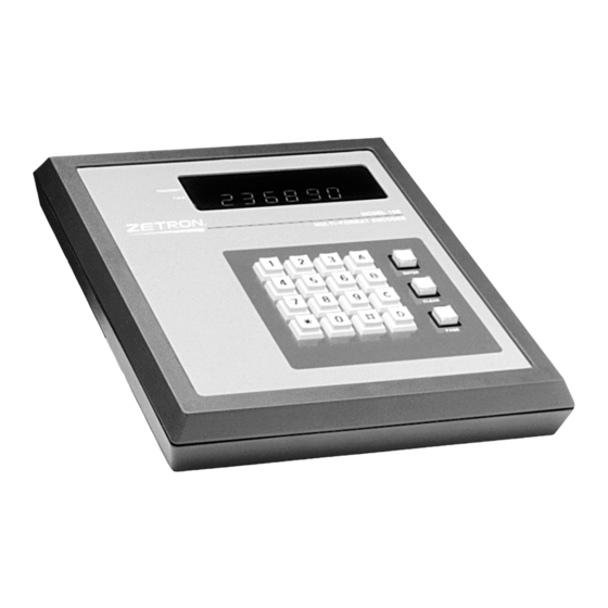
Following installation by qualified radio service personnel, turn on power to the encoder. The first number shown in the display is the Zetron order number. The unit then displays its software version number. Finally, the display clears and ends up showing one or more hyphens which indicate successful power up completion and readiness for operation. -
Page 26: Front Panel Display
Section 3. Operation FRONT PANEL DISPLAY Table 3. OPERATION-1 explains the meanings of the common display indications seen on the front panel of the encoder. In the table, “x” takes the place of any numeric digit. Table 3. OPERATION-1 Common Display Prompts Indication Meaning Ready to accept format leading digit from keypad. -
Page 27: Pager Number
Autopage The Model 15P can be programmed by the installer to start the paging sequence either automatically after the last digit of the pager code has been entered (Autopage = ON), or only after the PAGE key has been pressed (Autopage = OFF). Autopage is activated after the encoder has received the maximum number of digits allowable for the chosen format. -
Page 28: Autoscroll
Section 3. Operation “Programming System Parameters” in Section 5 for complete details. The encoder is shipped with the Autopage function off to allow the operator to review the pager number in the display before sending the page. If the chosen format allows a message to be sent, Autopage shows a message prompt. -
Page 29: Custom Stacks (Fixed Stack
The Model 15P can also be programmed with fixed stack pages that are held in the encoder's non-volatile memory. -
Page 30: Talk
Section 3. Operation all of the individual pager codes have been transmitted, regardless of what position the fixed stack number had in the keypad stack. The maximum number of pager capcodes that can be placed in a fixed stack is limited by the “stacks”... -
Page 31: Repage
Section 3. Operation pager number in a keypad stack is found to be invalid, the transmission halts and all remaining pager numbers are lost. 2. Checks for a channel busy input. If detected, the encoder blinks the display message “buSY” continuously at a rapid rate until an internal timer determines that the channel has been available for two seconds. -
Page 32: Optional Serial Port
OPTIONAL SERIAL PORT Power-Up Test The Model 15P encoder has no dip switches in order to configure it. Instead, the encoder’s configuration options are selected in Programming mode (see “Programming System Parameters” in Section 5). This means that nothing has to be set before applying power. -
Page 33: Special Keys
Section 3. Operation Operation When the power-up tests are complete, the following message is printed on the CRT screen: Model 15P Field Programmable, Ver: 2.1 Copyright, 1984-1996, ZETRON INC. KEYPAD ACTIVE: Any key activates CRT. Enter capcode: When the encoder is first powered up, it expects to receive commands from the keypad. All keys (0-9,A-D,*,#) typed at the encoder's keypad are displayed on the CRT. -
Page 34: Crt Paging Examples
CRT or computer which is connected to a Model 15P. Table 3. OPERATION-3 demonstrates a 5-tone page with talk time (assuming 5-tone is leading digit 0). Table 3. OPERATION-4 shows how to enter a POCSAG page with an alphanumeric format message to be sent (assuming POCSAG is leading digit 1). - Page 35 Section 3. Operation Table 3. OPERATION-4 Example of POCSAG Alpha-message Page from CRT YOU TYPE CRT PROMPT EXPLANATION Enter capcode: Ready for pager code Enter capcode: 0 Wrong leading digit Enter capcode: CTRL-C Start over Enter capcode: 11122334 11122334 POCSAG capcode Enter message: ENTER/RETURN Ready for message...
-
Page 37: Installation
4. INSTALLATION OPENING THE ENCODER ................4-1 WIRE ROUTING ....................4-1 GROUNDING .....................4-1 POWER SUPPLY....................4-1 AUDIO OUTPUT....................4-1 DIGITAL OUTPUT.....................4-2 MICROPHONE CONNECTION ................4-2 PUSH-TO-TALK....................4-2 DIGITAL MODE....................4-3 EXTENDING THE TALK TIME ...............4-3 ALPHA PAGING ....................4-3 SERIAL CRT INTERFACE................4-4 INTERFACE CONNECTOR ................4-4 Jumpers ....................4-7 ADJUSTMENTS ....................4-7 Audio Test Mode ..................4-7 Binary Test Mode ..................4-8 DTMF Output Test ..................4-8... -
Page 39: Opening The Encoder
The audio output from the encoder is obtained from TB1 pin 4. This pin is internally switched by the Model 15P's audio circuits between the tone generator output and the external microphone input. When idle and during Talk time TB1 pin 4 is normally connected... -
Page 40: Digital Output
Section 4. Installation DIGITAL OUTPUT The digital paging formats require very accurate timing reproduction of the binary waveform edges. To guarantee such accuracy, the terminal must be located in close proximity to the digital transmitter; typically a distance of 50 feet or less. It is also recommended that coaxial cable with a DC resistance of less than 100 ohms be used to carry the digital output signal. -
Page 41: Digital Mode
To simplify explanations from this point on, the CRT or computer used with the Model 15P will simply be referred generically to as the “terminal”. -
Page 42: Serial Crt Interface
Section 4. Installation SERIAL CRT INTERFACE The requirements for serial interface to the encoder are listed in Table 4. INSTALLATION- 1. Configure the terminal's serial communications parameters to match. Check jumper JP-14 on the PCB to find the baud rate. Table 4. - Page 43 Section 4. Installation Table 4. INSTALLATION-3. Connector TB2 Pin-out TB2-# Signal Function (not used) Ground RS-232 receive Serial data from CRT RS-232 ground Serial ground RS-232 transmit Serial data to CRT (not used) (not used) PTT common PTT relay common PTT N.O./N.C.
- Page 44 Section 4. Installation The drawing in Figure 4. INSTALLATION-1 illustrates the interface connector. ZETRON ENCODER 12 VAC/+14VDC INPUT 12 VAC INPUT SHIELD AUDIO OUTPUT TONE SYSTEM GROU EXTERNAL MIC AUDIO MIC INPUT CHANNEL BUS Y INPUT DIGITAL MODE DIGITAL OUTPUT TRANSMITTER PTT PTT N.O.
-
Page 45: Jumpers
Section 4. Installation Jumpers The jumpers listed in Table 4. INSTALLATION-4 are used to configure the Model 15P hardware for the system it is installed in. More detailed explanations and instructions for jumper placement are contained in the installation instructions. -
Page 46: Binary Test Mode
DTMF tone pair. All sixteen pairs are supported. Press the CLEAR key to exit this test and return to the normal operating mode. EXCEPTIONS Zetron engineers are available for consultation on exceptional installation connections not described above. CABLE OPTIONS Drawings for any option interface cables that were ordered with the encoder are included with your order. -
Page 47: Programming
5. PROGRAMMING OVERVIEW ......................5-1 PROGRAMMING SYSTEM PARAMETERS ...........5-3 System Programming Example..............5-4 Station ID Characters................5-5 Example ..................5-6 PROGRAMMING PAGING FORMATS ............5-7 About the Custom Calls Formats.............5-7 Two-Tone....................5-8 Programming Example ..............5-8 Five-Tone....................5-10 DTMF Format..................5-11 HSC Format .....................5-12 Reach Format ...................5-13 2805 Format .....................5-14 Alert Tones ....................5-15 Custom Two-Tone Format...............5-16 Brief Summary................5-17... -
Page 49: Overview
All programmable values are saved in nonvolatile memory when leaving programming mode. During power-up, the Zetron order number is momentarily displayed, followed by the installed software's version number. When the encoder is first powered up for the first time or is powered up without configurations or formats programmed, the LED display shows the prompt “SEtUP”. - Page 50 When the all the parameters for a given selection have been made, the Model 15P briefly displays the prompt “ ..” (four dots), indicating that all the parameters for that mode have been programmed.
-
Page 51: Programming System Parameters
Section 5. Programming PROGRAMMING SYSTEM PARAMETERS A description of the prompts encountered when programming system parameters is presented in Table 5-1 for easy reference. The mix of upper and lower case characters in the prompts simulate what is actually viewed on the LED display. To the right of the prompt is a description of what the prompt is asking for and what responses are valid. -
Page 52: System Programming Example
Section 5. Programming System Programming Example The Table 5. PROGRAMMING-2 is an example of the sequence of prompts and keystrokes for programming system parameters. Table 5. PROGRAMMING-2 System Programming Example Prompt Keystroke Explanation SEtUP C and CLEAR Displaying the SEtUP prompt indicates that no formats have together been programmed. -
Page 53: Station Id Characters
15 minutes and 22 WPM. The Model 15P will accept call signs up to ten characters in length. The call sign can use all 26 letters of the alphabet and the digits “0” to “9”. Because all of the programming of the Model 15P must be entered from the rather limited keypad, it is necessary to use two-digit combinations to represent all of the characters in the ID call sign. -
Page 54: Example
ID string anyone has programmed into the Model 15P. To enter a new ID, you simply start keying in the two-digit combinations for each character. As the second digit of each pair is entered, the encoder will display the proper letter or number for that entry. -
Page 55: Programming Paging Formats
Section 5. Programming PROGRAMMING PAGING FORMATS The following paragraphs describe the prompts encountered when programming paging formats. When the display reads “diGt=0”, selecting a digit between 0 and D will select the leading digit under which a paging format may be programmed. When only a single format is to be programmed in the encoder, a leading digit still needs to be selected for programming to proceed. -
Page 56: Two-Tone
When COdE = 0, this prompt requests the second tone group for a 100 call paging system. PLN= 0 When COdE = 1, this prompt requesting the Zetron code plan number (0 - 24) for 1000 call paging systems. For code plan numbers, see Section 7, "Motorola and GE Code Plans". - Page 57 Section 5. Programming Table 5. PROGRAMMING-5 Programming a Leading Digit for 2-Tone Prompt Keystroke Explanation SEtUP C and CLEAR The display indicates that no formats have been programmed. Hold the C and CLEAR keys down together to enter the programming mode.
-
Page 58: Five-Tone
Section 5. Programming Five-Tone For 5/6-tone format programming (full 100,000 call capacity) select the paging format prompt “5 tonE”, then press ENTER. Table 5. PROGRAMMING-6 shows and explains the prompts for this format. Table 5. PROGRAMMING-6 Five-Tone Format Prompts Major Conditional Prompt Prompt... -
Page 59: Dtmf Format
Section 5. Programming DTMF Format For DTMF encoding, select the paging format prompt “dtn.F”, and then press ENTER. Table 5. PROGRAMMING-7 shows and explains the prompts for this format. The maximum length for DTMF paging is eight digits. Table 5. PROGRAMMING-7 DTMF Format Prompts Major Conditional Prompt... -
Page 60: Hsc Format
Section 5. Programming HSC Format For Hexadecimal Sequential Code (HSC) for PG-50 pagers, select the paging format prompt “HSC” and then press ENTER. Table 5. PROGRAMMING-8 shows and explains the prompts for this format. Table 5. PROGRAMMING-8 HSC Format Prompts Major Conditional Prompt... -
Page 61: Reach Format
Reach is essentially a specialized form of two-tone paging. For the purposes of fitting it into the Model 15P, Zetron has taken 50 tones from the original group of 60 Reach tones and organized them into five tone groups. These five tone groups are then used to make up a 1000-call code plan. -
Page 62: 2805 Format
Section 5. Programming 2805 Format For 2805/1500-Hz pulse paging format, select the paging format prompt “2805”, and then press ENTER. Table 5. PROGRAMMING-10 shows and explains the prompts for this format. Table 5. PROGRAMMING-10 2805 Format Prompts Major Conditional Prompt Prompt Explanation tALH =... -
Page 63: Alert Tones
The Model 15P can transmit the audible Alert tones by themselves, just as though they were paging tones. This format allows the Alert tones to be assigned a leading digit. The Alert tone desired can be selected manually each time this feature is used, or a single Alert tone can be strapped to the leading digit. -
Page 64: Custom Two-Tone Format
Section 5. Programming Custom Two-Tone Format To program this format, select the “c2tonE” prompt from the format selection menu. Table 5-12 explains the various prompts that are used by this format, and Table 5-13 shows the keys that are used for editing. Table 5-12 Custom Two-Tone Format Prompts Prompt Explanation... -
Page 65: Brief Summary
The Custom Two-Tone format allows you to program the frequencies, their timings and gap duration on a capcode by capcode basis. All programming can be done from your bench without the need for a PC or assistance from Zetron. Here is a list of the Custom Two-Tone capabilities: x Each Custom Two Tone capcode may be from 1 to 4 digits long. - Page 66 Section 5. Programming Table 5-14 First Custom Two-Tone Page Display Keystrokes Explanation ##### Plug in the wall transformer. Display shows Z-number & version number during power up. Version 2.1 SEtUP SEtUP means no formats programmed yet. ConFIG C+CLEAR Display momentarily shows ConFiG to indicate that it is entering keys together programming mode.
- Page 67 Section 5. Programming Table 5. PROGRAMMING-15 Second Custom Two-Tone Page Display Keystrokes Explanation 902, ENTER Type in 902 for the next capcode and press ENTER. A1000.0 2000.0 1000.0Hz appears in the display as the default Tone A frequency. Type in 2000.0 Hz to replace it. A2000.0 ENTER Press ENTER to input the Tone A frequency.
- Page 68 Section 5. Programming Finally, the steps in Table 5-17 show how to save the two capcodes that were created in this example to the nonvolatile memory. Table 5-17 Saving the Custom Two-Tone Programming Display Keystrokes Explanation CLEAR Press the CLEAR key to exit the Custom Two-Tone format. diGt =0 CLEAR Press the CLEAR key again to exit programming mode.
-
Page 69: Pocsag Format
Section 5. Programming POCSAG Format For POCSAG tone-only and alpha/numeric pagers, select the POCSAG format prompt, and press ENTER. Table 5-18 shows and explains all of the prompts for this format. Table 5-18 POCSAG Format Prompts Major Conditional Prompt Prompt Explanation StrP = Number of capcode digits strapped within the encoder. -
Page 70: Nec Format
Prompt Explanation StrP = Number of capcode digits strapped in the Model 15P. A valid response is from 0 to 4 digits. Please note: if four digits are strapped, the encoder will be limited to 6-digit tone/numeric display operation only. -
Page 71: Golay (Gsc) Format
Prompt Prompt Explanation StrP = Number of capcode digits strapped the Model 15P. A valid response is from 0 to 4 digits. StP(n)= If StrP > 0, then this prompt requests the digit desired for the strap position shown. StP1= is always the first digit sent, StP2= is the next and so on. -
Page 72: Custom Dtmf Format
The Custom DTMF format allows you to send from 1 to 10 digits with a single capcode. All programming can be done from your bench without the need for a PC or assistance from Zetron. Here is a list of the Custom DTMF capabilities: x Each Custom DTMF capcode may be from 1 to 4 digits long. -
Page 73: Programming Example
Section 5. Programming Programming Example This example assumes no prior knowledge of the Model 15P. You will be taken from power up to programming. At the end of this exercise you will have programmed and edited two Custom DTMF capcodes and their data. The encoder will be programmed with the... - Page 74 Section 5. Programming You have now programmed one capcode and its data and are ready to program the next. The steps shown in Table 5-25 demonstrate how the encoder utilizes the data from the previous capcode as default data for the next capcode. Anticipating the next entry should speed the programming process for large Custom DTMF data bases.
- Page 75 Section 5. Programming Table 5. PROGRAMMING-27 shows how to save the two capcodes that were created in this example to nonvolatile memory. Table 5. PROGRAMMING-27 Saving Custom DTMF Programming Display Keystrokes Explanation CLEAR Press the CLEAR key to exit the Custom DTMF format diGt =0 CLEAR Press the CLEAR key again to exit programming mode.
-
Page 76: Custom Stack-Page Format (Fixed Stack)
Section 5. Programming Custom Stack-Page Format (Fixed Stack) To program this format, select the StACH prompt from the format selection menu.Table 5-28 explains the various prompts that are used by this format, and Table 5-29 shows the keys that are used for editing. Table 5-28 Custom Stacks Format Prompts Prompt Explanation... - Page 77 Section 5. Programming The Custom Stack format gives you the ability to send several pages from one capcode. The number of pages per stack is determined by the number of capcodes and messages that may be in the stack, which is limited the block of memory reserved for each stack. There is a worksheet at the end of Section 7 that can be used to determine whether or not all the pages/messages you wish to send can be fit into a single stack.
-
Page 78: Programming Example
Section 5. Programming Programming Example This example assumes no prior knowledge of the Model 15P. You will be taken from power up to programming. At the end of this exercise you will have programmed and edited a Custom stack. The encoder will be programmed with the following:... - Page 79 Section 5. Programming Table 5. PROGRAMMING-30 shows the steps required to program a stack containing the five pages and to set the Alert Tone and Talk time as shown. The Alert and Talk time used by any given stack is independent of the ones assigned to any individual pagers contained within that stack.
- Page 80 Section 5. Programming You have now programmed a stack and are ready to program another. The steps shown in Table 5. PROGRAMMING-31 demonstrate how to edit an existing stack. For this example, you will change the capcode 800 (entered in error) to 802 and add one more capcode (708) to the stack that was created previously.
-
Page 81: Important Things To Remember When Programming Stacks
Section 5. Programming Table 5. PROGRAMMING-32 Inserting Messages in a Stack for POCSAG Display Keystrokes Explanation Type in 100 for the stack number. St 100 ENTER Press ENTER to input the stack number. Alrt Type in 4 to give a “fast siren” Alert. Alrt ENTER Press ENTER to input the Alert value. - Page 82 Model 15P will “borrow” the necessary digits from the next capcode in the stack. This will result in several possible failure modes for this...
- Page 83 The Model 15P will display the pages as they are made, which should allow you to check whether or not the stack is going out as you intended. Even if you are not in a position to actually...
- Page 85 OUTPUT TESTS ....................6-2 Audio Test Mode ..................6-2 Binary Test Mode ..................6-2 DTMF Output Test ..................6-3 FAULT IDENTIFICATION................6-3 MODEL 15P TOP LEVEL PARTS LIST ............6-4 MODEL 15P MULTI-FORMAT ENCODER (702-9855B) .......6-5 Parts List ....................6-5 Schematic....................6-7 Silkscreen....................6-9 MODEL 15P SERIAL PORT PARTS LIST ............6-10 MODEL 15P SPARE PARTS LIST..............6-10...
-
Page 87: Repair
Zetron Model 15P Service Department at the same number. When calling Zetron for help, please have the serial number of the unit and/or the Zetron order number (the order number is momentarily displayed when powered up). If an error message is displayed by the unit following power up, please record this number as well. -
Page 88: Output Tests
Section 6. Repair OUTPUT TESTS Three output tests are provided to allow setting of the tone output levels. Cycle the unit's power to exit the output tests. Audio Test Mode Depress the A + CLEAR keys while at the normal idle prompt (- ) to activate the tone output test. -
Page 89: Dtmf Output Test
Section 6. Repair DTMF Output Test While the DTMF tone pairs are generated by a different source than the rest of the analog paging signals, they come out through the same final audio stages as the other analog signals and their level is adjusted using the same control, R26. If the Audio test has been done correctly, it is very likely that you will never need to test the DTMF tone pairs independently. -
Page 90: Model 15P Top Level Parts List
Section 6. Repair MODEL 15P TOP LEVEL PARTS LIST (Reference: 901-9313J) ITEM QTY PART NUMBER/REV. DESCRIPTION REFERENCE ---- --- ------------------ --------------------------- -------------------------- 220-0108 SCREW #440 ¼" 220-0109 SCREW #440 ¾" BOTTOM COVER 220-0110 440x3/16 NYLON SCREW KEYPAD 322-7256 32Kx8 CMOS EPROM... -
Page 91: Model 15P Multi-Format Encoder (702-9855B)
Section 6. Repair MODEL 15P MULTI-FORMAT ENCODER (702-9855B) Parts List ITEM QTY ZETRON P/N DESCRIPTION COMPONENT REF MFR. PART # ---- ----- ------------ --------------------- ------------------ --------------- 101-0033 22 OHM 101-0049 100 OHM R37 45 46 77 101-0065 470 OHM 101-0068... - Page 92 Section 6. Repair MODEL 15P MULTI-FORMAT ENCODER (702-9855B) Parts List (Continued) ITEM QTY ZETRON P/N DESCRIPTION COMPONENT REF MFR. PART # ---- ----- ------------ --------------------- ------------------ --------------- 321-6522 VIA/TIMER R6522 321-6803 MICROPROCESSOR 6803P 323-4015 DUAL 4-BIT SHIFT REG. U3-8 MC14015B...
-
Page 96: Model 15P Serial Port Parts List
Section 6. Repair MODEL 15P SERIAL PORT PARTS LIST (Reference: 950-9373A) ITEM QTY ZETRON P/N DESCRIPTION REFERENCE ---- ------ ----------- ---------------------------- --------------------------------- 317-5406 DUAL RS-232 DRIVER 709-7038 M23 PRT/TERM.CABLE MODEL 15P SPARE PARTS LIST (Reference: 951-9061B) ITEM QTY ZETRON P/N DESCRIPTION... -
Page 97: Model 15P Serial Port Connections
When interfacing the Model 15P to a CRT terminal instead of a PC, the connector is typically a male 25-pin D-connector instead of a female connector. This information is correct for most computers. - Page 99 5/6-Tone Format ..................7-5 DTMF TONE PAIR FREQUENCIES..............7-6 HSC TONE FREQUENCIES AND TIMINGS...........7-7 HSC Format .....................7-7 REACH ENCODING PLAN................7-12 Zetron Tone Groups for REACH Encoding ..........7-12 REACH Code Plan ..................7-13 REACH Tone Timing ................7-13 POCSAG DIGITAL FORMAT ................7-14 NEC DIGITAL FORMAT (D2/D3) ..............7-15 MOTOROLA GOLAY DIGITAL FORMAT .............7-16...
-
Page 101: Quick Reference
These tone groups and timings are shown in Table 7-1or Table 7-2. Motorola and GE Tone Group Frequencies Table 7-1 Zetron Tone Groups 1 to 7 Zetron Group No. Mfr. Tone Groups Mot 1... -
Page 102: Two-Tone Timing
Section 7. Quick Reference Table 7-2 Zetron Tone Groups 8 to 14 Zetron Group No. Mfr. Tone Groups Mot B Mot Z GE A' GE B' GE C' Mot 10 Mot 11 371.5 346.7 682.5 652.5 667.5 1472.9 1930.2 412.1 384.6... -
Page 103: Pager Capcode
Section 7. Quick Reference Each code plan in Table 7-4 through Table 7-6 is broken down into 10 blocks of 100 pager codes. The blocks are numbered 0 through 9. As you look at a certain 100-block within a certain code plan in the table, you'll see that it's referred to with a pair of numbers, such as 1+2 or 5+3. -
Page 104: Motorola And Ge Code Plans
1,2,4 1,2,5 1,2,6 1,3,4 1,3,5 1,3,6 1,4,5 1,4,6 Groups Used Table 7-5 Zetron Numbers Assigned to Motorola Code Plans “L” to “U” Zetron Codeplan Mfr Codeplan Pager Capcodes Mot L Mot M Mot N Mot P Mot Q Mot R... -
Page 105: 5/6-Tone Frequencies And Timings
Section 7. Quick Reference 5/6-TONE FREQUENCIES AND TIMINGS Table 7-7 Five-Tone Groups and Timings Tone Number CCIR ZVEI 1981 2400 1981 1124 1060 1124 1197 1160 1197 1023 1275 1270 1275 1164 1358 1400 1358 1305 1446 1530 1446 1446 1540 1670 1540... -
Page 106: Dtmf Tone Pair Frequencies
Section 7. Quick Reference DTMF TONE PAIR FREQUENCIES This diagram shows the tones actually generated by the Model 15P for DTMF signaling. Keys are from the 16 button keypad, all frequencies are in Hertz. Column Column Column Column --1-- --2--... -
Page 107: Hsc Tone Frequencies And Timings
Section 7. Quick Reference HSC TONE FREQUENCIES AND TIMINGS Table 7. QUICK REFERENCE-8 HSC Tones and Timings CCIR ZVEI (USA) 1981 2400 1981 1124 1060 1124 1197 1160 1197 1023 1275 1270 1275 1164 1358 1400 1358 1305 1446 1530 1446 1446 1540... - Page 108 Section 7. Quick Reference The address and service block are printed on the HSC pager in the following order: xxxxx-s- b, where xxxxx is the address, and s is the service block, as described below. b is the beep duration, which is not entered into the encoder. For multiple format or test-bench encoders, the appropriate leading digit must be entered first to select HSC format.
- Page 109 Section 7. Quick Reference Message Type Pager Entry Sequence Voice Message Call Alert 8 9 12345 3 PAGE Data “123456” 8 9 12345 7 PAGE 123456#PAGE Phone # “206-644-1300”, Extension “0000”, 8 9 12345 08 PAGE 206*644*1300 # 0000 # 99 Source “99”...
- Page 110 No priority, data only (no message formatting by pager) 12 characters # PAGE IMMEDIATE ZETRON FUNCTIONS No address or message required. Press the leading digit, if required, then the key for the selected function. All Immediate Functions use an All Call address of HSC code “A”s except where digits are strapped or a service block must be specified.
- Page 111 The pager is now in the “Learn Mode”. 4. Using the Zetron Model 15P, connected to the Maxon HSC-6000 pager via an RF link or direct audio input, enter the current capcode of the pager using the keypad, ignoring the RCC Capcode and beep time.
-
Page 112: Reach Encoding Plan
2523.0 1500.0 892.0 530.0 2437.0 1449.0 862.0 512.0 495.0 Zetron Tone Groups for REACH Encoding Zetron’s Reach tone-group assignment is shown in Table 7-11. Table 7-11 Zetron's Reach Tone-Group Assignment Tone Number 1980.0 1177.0 1400.0 832.0 588.0 2704.0 1608.0 1912.0 1137.0... -
Page 113: Reach Code Plan
Section 7. Quick Reference REACH Code Plan Zetron’s Reach code plans are listed in Table 7-12. Table 7-12 Zetron's Reach Code Plans Pager Indiv. Call Capcode Tone Groups Z5+Z3 Z1+Z2 Z2+Z1 Z3+Z4 Z4+Z3 Z1+Z4 Z4+Z1 Z1+Z5 Z5+Z1 Z3+Z5 NOTE For REACH group call, 0xx group is not present. Instead, ten group calls are accessible using pager numbers 000,011,022, ... -
Page 114: Pocsag Digital Format
Section 7. Quick Reference POCSAG DIGITAL FORMAT If any message function is repaged, a new message must be entered before paging. The old message is lost. No POCSAG pager numbers may be entered into the memory stack. DATA RATE: 512, 1200, or 2400 Baud CAPCODE ENTRY: xxxxxxx f (one or more x may be strapped) xxxxxxx... -
Page 115: Nec Digital Format (D2/D3)
Section 7. Quick Reference NEC DIGITAL FORMAT (D2/D3) If any message function is Re-paged, a new message must be entered before paging. The old message is lost. No NEC pager numbers may be entered into the memory stack. CAPCODE ENTRY: (NEC D2) Tone Only Page xxxxx... -
Page 116: Motorola Golay Digital Format
Section 7. Quick Reference MOTOROLA GOLAY DIGITAL FORMAT For any function that requests Talk, the interval will be given following transmission of the GSC address and message data. Speak when “tALK” is displayed. A pager Mute will automatically follow the Talk interval; “PAGE” will again be displayed. If any message function is Re-Paged, a new message must be entered before paging. -
Page 117: Motorola Metro Digital Format
Section 7. Quick Reference xxxxxx f PAGE D t PAGE ALPHANUMERIC TEST ENTRY: example = alphanumeric test message 1 or 2 Test message 1 = “ABCDEFGHJKLMNPQRSTUVWXYZ” (24 characters) Test message 2 = “0123456789:;<=>?*ABCDEFGHIJKLMNOPQRSTU VWXYZ[/]$%” (48 characters) MOTOROLA METRO DIGITAL FORMAT No METRO pager numbers may be entered into the memory stack. -
Page 118: Programming Functions Log
Section 7. Quick Reference PROGRAMMING FUNCTIONS LOG Use this Programming Functions Log to record the settings programmed into your encoder. This log will be a handy reference should changes be required. Copy these pages as necessary to record all leading digits programmed. Please Note: Throughout the following lists, 0 = No or Off, 1 = Yes or On SYStEM System wide parameters. - Page 119 Section 7. Quick Reference 5 tonE ___ = Leading digit for 5/6 Tone format Main Dependent Programmed Prompt Prompt Value Description tALH = Talk enable Yes/No PrE = Send preamble digit Yes/No StrP = # of strapped digits including PrE StP(n)= Strapped digit value #____________ rEPt =...
- Page 120 Section 7. Quick Reference rEACH ___ = Leading digit for Reach format Main Dependent Programmed Prompt Prompt Value Description tALH = Talk enable Yes/No StrP = # of strapped digits StP1 = Strapped digits #____________ 1St = First tone timing #/100ms GAP = Gap timing #/100ms 2nd =...
- Page 121 Section 7. Quick Reference POCSAG ___ Leading digit for POCSAG format Main Dependent Programmed Prompt Prompt Value Description StrP = # of strapped digits StP(n)= Strapped digits #____________ Fnct = Strapped Function code Yes/No diGt = Function digit 1 to 8 tALH = Talk enable Yes/No Baud =...
-
Page 122: Custom Calls Memory Requirement Worksheet
Section 7. Quick Reference CUSTOM CALLS MEMORY REQUIREMENT WORKSHEET The real capacity of the Model 15P for the Custom paging formats is determined by how much of its non-volatile memory has been used. This in turn is determined by which formats where used and how many pager capcodes were programmed under each format. -
Page 123: Custom Stack Memory Requirement Worksheet
Section 7. Quick Reference CUSTOM STACK MEMORY REQUIREMENT WORKSHEET As a general approximation the Custom Stack feature has a capacity of ten pager capcodes per stack. If your application requires more than ten pages in a single series, then you can put the capcode of another fixed stack in the last position and the next stack will follow the first without interruption. -
Page 124: Model 15P Configuration Sheet
Section 7. Quick Reference MODEL 15P CONFIGURATION SHEET Serial number: ________________________ Zetron order number: ________________________ Model number: 901-9313 Rev ___________ Software revision: 601-0434 Rev.___________ Date: ________________________ Installed options: Analog option x Two Tone x Five Tone x DTMF x HSC...
Need help?
Do you have a question about the 15P and is the answer not in the manual?
Questions and answers