Table of Contents
Advertisement
Quick Links
Advertisement
Table of Contents

Related Manuals for ZETRON Model 25


Summary of Contents for ZETRON Model 25
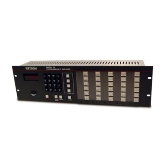
- Page 1 Model 25 Programmable Encoder Product Manual 025-9567E...
-
Page 3: Limited Warranty
Zetron Products or Zetron Accessories, or refund the purchase price, at Zetron’s option, after return of such items by buyer to Zetron. Shipment shall be paid for by the buyer. No credit shall be allowed for work performed by the buyer. -
Page 4: Regulatory Compliance
Statements Regulatory Compliance FCC Class A User Information This equipment has been tested and found to comply with the limits for a Class A digital device, pursuant to Part 15 of the FCC Rules. These limits are designed to provide reasonable protection against harmful interference when the equipment is operated in a commercial environment. -
Page 5: Table Of Contents
Channel Busy Monitoring ................22 Keying Method ..................23 Calling Sequence Summary ..............24 RELAY TIMING DIAGRAM ................28 ENCODER INSTALLATION OVERVIEW ......................29 INSTALLATION PRECAUTIONS ..............29 RFI Caution ....................29 Proper Grounding of the Model 25 ............29 025-9567E... - Page 6 Contents Connecting the Power Supply to the Model 25 ........31 INSTALLATION PROCEDURE ................31 Initial Conditions ..................31 Procedure ....................31 INITIAL TESTING .....................31 Deviation ....................32 Verification Mode ..................32 Serial Port Control ...................33 DISASSEMBLY AND CIRCUIT LOCATION ..........33 ...
- Page 7 PROGRAMMING SECTION 6 - REMOTE CONTROL SETUP .....96 PROGRAMMING ENCODER FROM SERIAL PORT OVERVIEW ......................99 CONNECTING TO THE SERIAL PORT ............99 MODEL 25 CONFIGURATION PROGRAM ............101 The Program Disk ..................101 Program Features ..................102 “Installing” and Running the Program .............102 ...
- Page 8 Motorola and GE Tone Group Frequencies ..........120 Motorola and GE Code Plans ..............121 General Encoding Plans ................122 Model 25 Plan Numbers for Two-Tone 1000-Call Code Plans ....122 Reach Encoding Plan ................123 Zetron Tone Groups for Reach Encoding ..........123 ...
-
Page 9: Overview
The Model 25 provides several innovative features. One of these features is the ability to send multiple calls over automatically selected channels by the press of a single Instant Call pushbutton. -
Page 10: Display
Introduction There are two basic modes of operation for the Model 25 encoder; remote control and instant call modes. In remote control mode, input is accepted in ASCII from the RS-232 compatible Computer Port, but the Instant Call panels are disabled. In instant call mode the Instant Call panels are enabled but remote control is inhibited. -
Page 11: Keypad
There is more information on the “Keypad Stack” function later in this section. RESET key resets the Model 25 from any operating condition, and returns it to the “Idle RESET State”. -
Page 12: Instant Call Buttons
As many as 16 Instant Call buttons may be pressed at one time, the Model 25 will send the pages of each button in the order in which they were pressed. -
Page 13: Specifications
SPECIFICATIONS GENERAL Signaling Formats Motorola, GE, or Reach two-tone Quickcall 1 “two plus two” Five/six-tone sequential Plectron and custom calls 2805Hz rotary dial DTMF Digitone Golay Sequential Consult factory for additional formats Call Capacity 13 blocks of mixed formats, each block capacity is: Two-tone Full code plan capacity ( 1000 calls ) Quickcall 1... -
Page 14: Electrical
Specifications ELECTRICAL Frequency Range 250 to 3276 Hz Frequency Accuracy +/- 0.1% Audio Output Drive Balanced, 600 ohm impedance Audio Amplitude Adjustable, -60dBm to -10dBm Paging Output ( 0 - 0.75 V p-p, into 600 ohms) (Tone Output 1) ( may be field altered to +7dBm maximum) Audio Amplitude Adjustable, 3.6 V p-p max. -
Page 15: Special Features
Specifications SPECIAL FEATURES Display Four 0.40", 7-segment readouts Utilizes some alphanumeric operator messages Low RFI non-multiplexed drive Channel busy LEDs 4 indicators showing status of channels Key switches 16-key “DTMF” keypad, other keys are provided for channel selection, stack editing, and alerts Instant Call keys 29 Instant Call key switches with integral LEDs used to show status. - Page 16 Specifications 025-9567E...
-
Page 17: Operation
OPERATION OVERVIEW This section covers normal operation of the Model 25 once it has been installed and programmed. POWER ON When power is applied to the Model 25, it automatically begins an extensive self-test. While the encoder is testing, the LEDs of the encoder and all attached Instant Call panels will be illuminated. -
Page 18: Using The Keypad
Table 1 shows the required input for each of the formats supported by the Model 25. Note that the leading block digit “b” must be in the range 1-9, A, B, C, or D. The actual block digit used to access the given format depends on the programming. -
Page 19: The Keyboard Stack
Operation After the encoding information (call number) has been entered it may be accumulated into the keyboard stack, sent immediately, or in the event of an entry error, erased. The Keyboard Stack The keyboard stack provides a means of accumulating several calls prior to sending any of them. -
Page 20: Sending Live Calls
Operation seconds, the display will stop blinking and the ability to re-page the keyboard stack will be lost. Even though the display is not cleared after a send, the encoder is still in the idle state and new encoding information may be entered as described previously. Sending Live Calls The live formats (live DTMF or live ROTARY DIAL) allow the encoding tones to be sent as each digit is pressed. -
Page 21: Displaying The Time
Accessing the Call Stack As a standard feature, the Model 25 contains 206 programmable call stacks, one call stack for each of the possible 206 Instant Call buttons. A call stack is specified by a four digit number which always starts with a leading digit of “0”. -
Page 22: Instant Call Key Numbering
Instant Call Key Numbering The Model 25 system allows the connection of up to three full sized Instant Call panels for a total of 206 individual Instant Call keys. The total panel count, however, is not restricted to three since two, or more, Auxiliary panels may be configured to operate in parallel (same panel address). - Page 23 Operation Each Instant Call key represents a call stack via a four-digit position dependent number. The number generated by each key is in the form “ ”. The meaning of each digit is: 0prc “ ” leading digit used to access the stack block “...
-
Page 24: Remote Control Operation
Remote control operation allows remote access to all encoder functions. Compatible ASCII RS-232 serial devices such as CRTs, printers or computers may be attached to the Model 25 via the DB9S computer port connector. In addition to the normal receive and transmit signals, the Computer Port also supports a Clear-To-Send (CTS) signal which may be used to indicate that the attached device is not ready to accept encoder output. -
Page 25: Call Logging
Operation Table 4. Remote Control Characters for Model 25 Character ASCII Hex Code Operation 0 to 9 30 to 39 same as keypad 0 to 9 A to D 41 to 44 same as keypad A to D same as keypad *... - Page 26 Operation Table 5. Keypad or Remote Input versus Encoder ASCII Output Keypad Input Remote ASCII Input Encoder ASCII Output 0 - 9 0 - 9 echoes input A - D A - D echoes input echoes input echoes input ENTER LINE FEED (control-J) ' (apostrophe) CLEAR ENTRY...
-
Page 27: Setting The Clock
Operation ---------SEND 1 Send #1 was origination RELAYS:---5---1 Control relays 5 and 1 were used BUSY Channel was busy at start, but became idle 13:47:50 24 hour time at start where PTT closes 2123 1st call, block 2, number 123 4A2B4 2nd call, block 4, number A2B4 512345... -
Page 28: Causes For Error Beeps
The encoder will again be in the normal operating mode (idle state) awaiting call instructions. CAUSES FOR ERROR BEEPS The following is a list of causes for error beeps from the Model 25 encoder during normal operation or calling sequences. Single beep, display not blinking ... - Page 29 Operation When key pressed: ALERT The number in the display is greater than three. When key pressed: CLEAR ENTRY The display is blank AND the keyboard stack is empty (nothing to clear). When key pressed: ENTER The number entered represents a call stack (block 0), OR the display is blank (nothing to enter), OR there are less than the minimum number of digits for the chosen format.
-
Page 30: The Calling Sequence
Operation THE CALLING SEQUENCE The calling sequence involves the keying of the audio, PTT, and control relays as well as the sampling of the channel busy inputs and the generation of tones. There are several programmable parameters that are helpful in tailoring the calling sequence to particular applications. -
Page 31: Keying Method
Operation This table shows the control relays programmed against each of the four keys. The SEND channel busy input number for a key always matches the number of the key. SEND SEND Control Relays Channel Busy SEND Key Programmed Input Used - - - - - - - 1 - - - - - - 2 - - - 6 - - 3 - -... -
Page 32: Calling Sequence Summary
Operation The other method is called Momentary Channel Select. Using this method, the selection of one or more console channels may be performed prior to sending a call. After the call is sent, the channels used for the send will remain selected for the voice message that may follow. Using this method, the control relays momentarily pulse a selecting signal to the console just prior to sampling the channel busy and closing the PTT. - Page 33 Operation Is last call a custom call with alert? :Yes - Print alert Generate 3 seconds of alert Open audio relay Print time (if time clock installed) Print bar Issue one beep Wait one second for another send Send command received? :Yes - Process send again at step 1.
- Page 34 Operation Is last call a custom call with alert? :Yes - Print alert Generate 3 seconds of alert Open audio relay Display time (if time clock installed) Print bar Issue one beep Wait one second for another Instant Call Instant Call received? :Yes - Process call again at step 1.
- Page 35 Operation Direct Keying Is PTT still closed and are the currently closed control relays same as the desired control relays? :Yes - Skip remaining steps here Open PTT relay Open control relays Wait 150 milliseconds SAMPLE CHANNEL BUSY Is channel busy used and has it been busy for over 30 seconds? :Yes - Skip remaining steps here Close programmed control relays Wait 150 milliseconds...
-
Page 36: Relay Timing Diagram
Operation RELAY TIMING DIAGRAM 025-9567E... -
Page 37: Encoder Installation
ENCODER INSTALLATION OVERVIEW This section of the manual covers the installation of the Model 25 Encoder panel (with or without keypad and display). The installation of the Auxiliary panel is covered in the next section. It is highly recommended that this equipment be installed by technicians with experience in the land mobile radio area of electronics. - Page 38 Encoder Installation Figure 4. Proper Grounding for the Model 25 MODEL 25 ORANGE BROWN WIRE TO CONSOLE GROUND YELLOW GREEN POWER SUPPLY 024-0104A Figure 5. Model 25 Power Supply Connection 025-9567E...
-
Page 39: Connecting The Power Supply To The Model 25
Mount the Model 25 and connect its PTT and Control relays to the appropriate inputs on the console. Connect the TX audio lines from the Model 25 to the appropriate inputs on the console. Connect the power supply to the Model 25. -
Page 40: Deviation
Encoder Installation Deviation The encoder can continuously generate a sequence of three tones for use in determining the proper tone output level and the proper pre-emphasis or de-emphasis. The deviation test consists of a 500 Hz tone, followed by a 1000 Hz tone, followed by a 2000 Hz tone, each tone lasting four seconds. -
Page 41: Serial Port Control
Encoder Installation Serial Port Control The serial port of the encoder is used to communicate with devices attached to the computer port or the instant call panels depending on the state of the “RMT-CTL” signal. A problem in the wiring of either the auxiliary panels or remote control devices may result in a non- functional encoder. -
Page 42: Keypad Enable/Disable
Encoder Installation Figure 6. Disassembly Diagram for the Model 25 Keypad Enable/Disable The keypad of the encoder may either be enabled or disabled by the placement of the jumper, JP2, on the encoder board (702-0312). If use of the keypad is necessary then the jumper must be in the “enabled”... -
Page 43: Display Scroll Enable/Disable
Encoder Installation It is possible to remotely enable or disable the keypad with a SPST switch wired across the “A” position stakes of the jumper, but the length of the wire used should be kept under 23 cm (9 inches). If the jumper is changed while power is applied then the key may need to RESET be pressed to reconfigure the encoder action. -
Page 44: Computer Port Connector Position
Encoder Installation 0312). The presence of R23 will cause the audio level adjustment range to be -60dBm to - 10dBm (0.75 V peak-peak max). The absence of R23 will cause the audio level adjustment range to be -60dBm to +7 dBm (5.0 V peak-peak max). If less than -10dBm is needed, then the lower adjustment range is recommended since otherwise a precise level adjustment via the four-turn potentiometer will be hard to achieve. -
Page 45: Instant Call Left Column Function
JUMPER AND SWITCH SETTINGS If the internal options of the Model 25 need to be changed in order to meet the needs of the system, the encoder should be opened and the changes made prior to the encoder being installed in the console. -
Page 46: Programming Enable/Disable Switch
Programming Enable/Disable switch on the encoder board (702-0312). The switch can be accessed on the rear panel of the Model 25. The encoder will ignore any attempt to access any programming mode from the keypad when the switch is in the disabled position. The encoder will operate properly with the switch in either position. -
Page 47: Rear Panel Connections
B AUDIO N.O. B audio switch normally open AUDIO N.C. B audio switch normally closed Table 9. P2 Connector Pinouts on Rear Panel of Model 25 P2 Pin Label Function TONE OUTPUT 2A external monitor speaker, 4Ω to 8Ω speaker TONE OUTPUT 2B external monitor speaker, 4Ω... -
Page 48: Transmitter And Console Control
* Jumper “LOOP OUTPUT” to “LOOP INPUT” if no auxiliary Instant Call panels are used. Transmitter and Console Control The Model 25 is designed to directly control from one to eight channels or transmitters, singly or simultaneously. The encoder achieves transmitter or console control through its eight control relays, its single DPDT Push-To-Talk (PTT) relay and its single DPDT Audio Steering relay. - Page 49 Another programmable channel control parameter is the transmitter key-up delay. The key- up delay that is programmed is used for all channels or transmitters that the Model 25 controls. The transmitter key-up delay is the duration between closure of PTT and the beginning of encoding tones.
-
Page 50: Channel Busy Monitor
Connect to P1-pin 1 Ground Connect to P1-pin 3 Channel Busy Monitor There are four common ground inputs on the Model 25 that are designed for monitoring channel status. Each of the channel busy inputs are associated with a particular key. SEND... -
Page 51: Audio Output/Muting
The subsection “Inside the Encoder” describes the way the impedance is selected. Audio Output/Muting The audio section of the Model 25 consists of a balanced 600Ω audio output and a DPDT audio muting (switching) relay. The audio muting relay will close (common connects to normally-open) when encoding or alerting tones are being generated. -
Page 52: Auxiliary Panels
Auxiliary Panels The connection between the Model 25 encoder and the auxiliary instant call panels is done via the signals labeled “LOOP INPUT” and “LOOP OUTPUT”. The loop uses RS-232C compatible signals and an ASCII asynchronous serial communications protocol. Both the encoder and auxiliary panels have the loop connections. -
Page 53: Computer Port
Encoder Installation COMPUTER PORT The computer port on the Model 25 encoder is compatible with RS-232C signals and uses an asynchronous ASCII serial communications protocol. The DE9 computer port connector socket contains four active RS-232C compatible signals; (clear- TX DATA... - Page 54 Polarity of the signal: busy on “space” or “mark” levels Call logging: disable or enable logging output. Table 14. Model 25 Computer Port Pinout Label/Function DTR (data-terminal-ready) provides “space” (pull-up to +12v via 330) N/C (no connection) TX DATA (transmit data) RX DATA (receive data) “break”...
-
Page 55: Panel Labels
Encoder Installation RMT-CTL jumper to pin 7 PANEL LABELS The area in between the instant call key columns is designed to hold labels for the keys to the right of the area. The plastic overlay covering the label area serves to protect and retain the instant call labels. -
Page 56: Software Updates
(702-0312) must be changed. When the new EPROMs are received from our factory, they should replace the EPROMs currently in the encoder. Because the Model 25 Encoder has been on the market for some time, some technicians find themselves upgrading from much older software versions (for example version 1.7 or 1.8). - Page 57 Encoder Installation 3. Place the new EPROMs, labeled U5 and U7, into the sockets with the corresponding labels. CAUTION These devices must be oriented in the proper direction or they will be destroyed. The notch in one end of the device must match the notch in the destination socket. The notch must face the top of the digital encoder board.
- Page 58 Encoder Installation 702-0312 M25 ENCODER BOARD Figure 8. Model 25 Digital Board Component Locations 025-9567E...
-
Page 59: Auxiliary Panel Installation
This section of the manual covers the installation of one or more Model 25 Auxiliary Panels in a system to augment the Model 25 Encoder. All of the cautions and warnings shown on page 29 for the Model 25 Encoder also apply to the Auxiliary Panel. -
Page 60: Connecting Power
OUT: CLEAR KEY CLEARS SELECTIVE LEDs Slot is centered in the unit rear panel. Figure 9. Model 25 Auxiliary Panel Rear Connections CONNECTING POWER The power is connected to the encoder via the two spade lug connectors (see Figure 10). Two mating female crimp connectors are supplied with the auxiliary panel. -
Page 61: Panel Labels
Auxiliary Panel Installation Figure 10. Power connections to Model 25 Auxiliary Panel The power required is +11 to +14 VDC at 1 ampere maximum. The fuse visible in the back panel cutout should be an AGC 1 ampere slow-blow. Figure 11 shows the suggested interconnection of the auxiliary panel. - Page 62 Auxiliary Panel Installation 025-9567E...
-
Page 63: Troubleshooting
25 Encoder. POWER-ON SELF-TEST By design, the Model 25 is software-intensive in order to minimize the number of components that may fail. The built-in self-test, which is automatically run when the encoder is powered-on, checks the displays, internal digital circuitry (microprocessor and memories), and displays the results on the front panel using the encoder status display and the Instant Call LEDs. - Page 64 Troubleshooting Table 16. Error Codes for Power-on Self-test Encoder Error Code Probable Failure Cause Err0 Instant Call Panel(s) or Loop connection(s) Encoder Bd: U30, U21, U26-U29, J4, Driver Bd: U8, U1-U4, U9, J3, J1 Err1 Wrong microprocessor mode Encoder Bd:, U19, U21,U29 Err2 Microprocessor software memory (EPROM) bad Encoder Bd: U5-U7, U1-U4, U18,...
-
Page 65: Continuous Self-Test
Troubleshooting Table 17. Error Codes for Instant Call Panel Faults Instant Call Error Code (Right column LEDs) Probable Failure Cause ● (on) Microprocessor temporary memory (RAM) bad ● (on) Driver Bd: U4 ● (on) ● (on) ● (on) ● (CLEAR key on) ○... - Page 66 Troubleshooting the DTMF pad show a single character representation, but the other keyboard keys show the two character representations in Table 18. Table 18. Keyboard Test Mode Responses Display SEND 1 (top send key) SEND 2 SEND 3 SEND 4 (bottom send key) ALERT ENTER CLEAR ENTRY...
-
Page 67: Instant Call Key Test
Troubleshooting INSTANT CALL KEY TEST While the encoder continuous self-test is executing, the Instant Call panels will also execute a continuous self-test. This Instant Call self-test can be changed to an Instant Call key test. The Instant Call key test is initiated (only during continuous self-test) by holding down a key on the Instant Call panel to be tested. - Page 68 Troubleshooting Fault Possible Cause Beeper will not sound but Encoder Bd. connection bad (J1, or check cable). display decimal point Cable between Encoder and Driver Boards bad. illuminates when beeper would Driver Bd. beeper circuit faulty (J3, C11, LS1). normally sound. Decimal point will not illuminate Cable between Encoder and Front Panel boards bad.
- Page 69 Troubleshooting Fault Possible Cause Channel busy indicators Channel busy input floating at high impedance (check jumpers apparently out of control. on Encoder Bd.). Channel busy input not connected properly. Front Panel Bd. channel busy circuit faulty. Encoder Bd. display driver faulty (U8, J2, U19). Cable between Encoder and Front Panel boards bad.
-
Page 70: Instant Call Fault Identification
Troubleshooting Fault Possible Cause Pressing a keypad key causes Encoder Bd. Block/Format parameter memory changed or encoder to become corrupted. This may happen if the software has been changed unresponsive or causes display in the encoder (U3- U7). Fix this problem by clearing the to show undefined character(s). - Page 71 Troubleshooting Fault Possible Cause One row of keys cannot be Driver Bd. circuit bad (U4, J4, J5, U9). detected. Switch Bd. circuit bad (RP1, PR2, U1, P1). One column of keys cannot be Driver Bd. circuit bad (U4, J4, J5, U9). detected.
- Page 72 Troubleshooting 025-9567E...
-
Page 73: Programming Encoder From Front Panel
This eliminates the possibility of accidentally entering a section. Once in the section the Model 25 will prompt you for an entry to the first question. All of the questions can be answered with a 1- to 5-digit entry from the keypad. -
Page 74: The Question Loop
Figure 12. The Question Loop for Model 25 Programming THE IDLE STATE To enter one of the programming sections the Model 25 must first be in the “Idle State”. The idle state is when the Model 25 is not performing any operation but rather “waiting” for the press of an Instant Call button, entry from the keypad, or entry from a remote CRT or computer. -
Page 75: Entering A Programming Selection
ENTERING A PROGRAMMING SELECTION While the Model 25 is in the idle state any of the six sections may be entered. This is done by a two-key sequence as shown below, if configuring the Model 25 from the keypad. If configuring from a CRT or computer, a “P”... - Page 76 4 = Clear All Sections (reset entire unit to default settings) Press a “4” to clear the entire encoder. The Model 25 is now clearing all sections When it is finished the Model 25 will automatically return to the idle state. 025-9567E...
-
Page 77: Programming Section 2 - Tone Format Selection
The display will prompt for this question by displaying: The valid choices are: 1 = Change Settings - Entering a “1” will instruct the Model 25 to continue on to “Question: b”. 2 = Print All Settings - Entering a “2” will instruct the Model 25 to print the settings of all questions in this section to the printer or CRT display connected to the serial port. - Page 78 We will use the following example to demonstrate its purpose. Assume your Model 25 was ordered with Motorola Two-Tone, Custom Calls, DTMF, and Motorola (2+2). Both the Motorola Two-Tone and Custom Calls require a 3-digit entry. The DTMF and Motorola (2+2) formats require a 4-digit entry.
-
Page 79: Question "F" - Format Assignment
Once you have selected a leading digit to work on, the unit will now display: Here, a format will be assigned to the leading digit selected in “Question b”. The Model 25 will allow only those formats ordered to be assigned to leading digits. If entry of a nonresident format is selected the Model 25 will again display the “Question F”... - Page 80 The 3-digit number entered determines which of the relays will be activated when a call from this leading digit is to be sent by the Model 25. Table 22 shows the values assigned to each of the eight control relays.
- Page 81 The expected entry for this question is a single digit. Table 24 lists the timings supported by the Model 25. Please note that if you selected Reach as the paging code plan, the alternate timings “6” and “7” are used.
- Page 82 During the time that the Model 25 is loading this information to memory, the display will appear as shown here.
-
Page 83: Motorola (2+2) Quick Call 1
Programming - Front Panel Once the Model 25 completes the loading procedure, it will return to the first question in the two-tone programming section, “Question “bo”” on page 69. You may select another leading digit to format or press to exit the programming mode back to the idle state. -
Page 84: 5/6-Tone Sequential (Motorola)
RESET memory, otherwise incorrect information could be loaded requiring reprogramming. Once the Model 25 completes the loading procedure, it will return to the first question in the two-tone programming section, “Question “bo”” on page 69. You may select another leading digit to format or press to exit the programming mode back to the idle state. - Page 85 The second “address” must be sent by the encoder in order for the pagers to react to it. The Model 25 is capable of single or dual address operation. The encoder is looking for a single-digit response (0 to 1) for this question.
-
Page 86: Dtmf
Programming - Front Panel DTMF Question 1 - Channel Select Relays This question works the same way for most paging formats. Please see “Question 1 - Channel Select Relays” on page 72 for a description. Question 2 - Preset or Live The encoder expects a single-digit response to this question (0 or 1). -
Page 87: 2805/1500 Hertz Rotary Dial
RESET memory, otherwise incorrect information could be loaded requiring reprogramming. Once the Model 25 completes the loading procedure, it will return to the first question in the two-tone programming section, “Question “bo”” on page 69. You may select another leading digit to format or press to exit the programming mode back to the idle state. - Page 88 During the time that the Model 25 is loading this information to memory, the display will appear as shown here.
-
Page 89: Alert Tone Format
RESET memory, otherwise incorrect information could be loaded requiring reprogramming. Once the Model 25 completes the loading procedure, it will return to the first question in the two-tone programming section, “Question “bo”” on page 69. You may select another leading digit to format or press to exit the programming mode back to the idle state. - Page 90 Programming - Front Panel Question 2 - Beep Tone Frequency The encoder expects a 5-digit response to this question (02500 to 32767). This entry sets the tone frequency used to generate the beep alert tones. It has no affect on any of the other alert tones, but some entry must be made for this question in order to continue through the format question loop.
-
Page 91: Digitone
RESET memory, otherwise incorrect information could be loaded requiring reprogramming. Once the Model 25 completes the loading procedure, it will return to the first question in the two-tone programming section, “Question “bo”” on page 69. You may select another leading digit to format or press to exit the programming mode back to the idle state. - Page 92 RESET memory, otherwise incorrect information could be loaded requiring reprogramming. Once the Model 25 completes the loading procedure, it will return to the first question in the two-tone programming section, “Question “bo”” on page 69. You may select another leading digit to format or press to exit the programming mode back to the idle state.
-
Page 93: Golay Sequential
Programming - Front Panel Golay Sequential The Zetron Model 25 Programmable Encoder supports signaling of Golay pagers according to Motorola function plan A. The available types of signaling are: tone, voice, and numeric data. Alphanumeric data is not supported by the Model 25. -
Page 94: Programming Section 3 - Custom Call Setup
RESET memory, otherwise incorrect information could be loaded requiring reprogramming. Once the Model 25 completes the loading procedure, it will return to the first question in the Two-Tone programming section, “Question “bo”” on page 69. You may select another leading digit to format or press to exit the programming mode back to the idle state. -
Page 95: Programming A Custom Call
At the following prompt, enter a three-digit number to identify this particular custom call (valid range is 000 to 195). The custom call question loop must be completed for each custom call programmed into the Model 25. This step is referred to as Question “0”. Question 1 The following prompt is for question “1”. - Page 96 Programming - Front Panel Question 2 The following prompt is for question “2”, which sets the tone frequency of the first tone in the custom call. The encoder requires a 5-digit response to this question (02500 to 32767, or 00000). The range is 250.0 Hz to 3276.7 Hz in increments of 0.1 Hz. Entering all zeros generates no tone.
-
Page 97: Programming Section 4 - Instant Call Button Setup
RESET memory, otherwise incorrect information could be loaded requiring reprogramming. Once the Model 25 completes the loading procedure it will return to the first question in the Custom Call programming section, “Question “bo”” on page 69. You may program another custom call or press to exit the programming mode back to the idle state. - Page 98 At the following prompt, press the particular instant call button to which you are assigning a page (or pages). The instant call question loop must be completed for each instant call button programmed into the Model 25. This step is referred to as Question “C”.
- Page 99 SEND begin to load all changes made in this section to memory to be used until new changes are made. During the time that the Model 25 is loading this information to memory, the display will appear as shown here.
-
Page 100: Programming Section 5 - General And Send Button Setup
At this point, the programming question loop forks into either the General Operations branch or the Send Button branch. At the end of either branch, the Model 25 saves the new settings and returns to the beginning of the main General and Send Button loop at step 2. - Page 101 (enter 00). A typical value for this parameter is 1 second (enter 10). This sets the delay time between the Model 25 keying PTT and the generation of the first paging tone. Question 3 - Review Before Send At the Question 3 prompt, enter a single-digit response (0 or 1) enable or disable the Review Before Send function.
-
Page 102: Send Button Branch
Most consoles require some sort of “simul-select” button to be pressed in order to allow the selection of more than one channel simultaneously. Setting this parameter to “1” results in the Model 25 using the Tone Relay as a simul-select relay. When set to “0”, the tone relay is used for its original purpose. - Page 103 During the time that the Model 25 is loading this information to memory, the display will appear as shown here.
-
Page 104: Programming Section 6 - Remote Control Setup
RESET memory, otherwise incorrect information could be loaded requiring reprogramming. Once the Model 25 completes the loading procedure, it will return to the first question in the General and Send Button programming section, “Question Ao_” on page 92. You may program a Send button, make another pass through the General programming, or press to exit the programming mode back to the idle state. - Page 105 At the following prompt, the encoder expects a single digit response (0 or 1) indicating whether or not the Model 25 should send a “Bell” character (Control + G) out the serial port whenever it sounds its own annunciator. The default setting is “0”.
- Page 106 RESET memory, otherwise incorrect information could be loaded requiring reprogramming. Once the Model 25 completes the loading procedure it will return to the first question in the General and Send Button programming section, “Question do_” on page 96. You may...
-
Page 107: Programming Encoder From Serial Port
HyperTerminal™ or ProComm™) or with the M25 Configuration Utility provided by Zetron. This section covers connecting a PC to the serial port of a Model 25 in order to program it. It will also cover using the PC to save copies of the unit programming to a disk file and restoring the unit with that file. - Page 108 “space” or “mark” levels Call logging: disable or enable logging output. The pin definition of the DE9 computer port connector socket is listed in Table 27. Table 27. Model 25 Computer Port Pinout Label/Function DTR (data-terminal-ready) provides “space” (pull-up to +12v via 330)
-
Page 109: Model 25 Configuration Program
While it is not necessary to use the Model 25 Configuration Program to communicate with and program the Model 25, this simple utility has been designed to streamline these tasks and is provided free along with every Model 25. While most of the programming capabilities remain available when using generic terminal emulation software, there are a few capabilities that are only available when using the Model 25 Configuration Program. -
Page 110: Program Features
600 baud and again at 150 baud in an attempt to determine at which rate the Model 25 is currently set. Once the proper baud rate has been determined, the edit screen will be displayed with the proper baud rate, Model 25 software version, and Configuration program software revision. -
Page 111: Configuration Program Operation
Figure 14. Figure 14. Model 25 Configuration Program When Idle The Model 25 firmware version is displayed in the upper right of the window (2.40) and the Configuration Program version is displayed at the lower left (1.5). The program is now operational and in the “Idle” state. Entering the letter “P” instructs the Model 25 to respond with the Main Program Menu. -
Page 112: Serial Programming Command List
If this feature is set to the ON position, all information that appears on the screen will also be sent to the printer (this only applies to a printer physically connected to the parallel printer port of the PC). This feature should be used to generate a printout of your current Model 25 configuration. - Page 113 F3 Function Key - Download If required, a configuration file may be downloaded to the Model 25 in order to restore the encoder configuration. The key is used to initiate the download process.
- Page 114 “Creating a Configuration Printout” on page 107 for more information. Once the Model 25 has been configured, the entire configuration may be uploaded to the computer for storage onto disk. This provides a safe way to record and back up the current configuration for later downloading to the Model 25.
-
Page 115: Creating A Configuration Printout
Programming - Serial Port Software Version 2.10 or Earlier If the Model 25’s software version is 2.10 or earlier, then once the file name has been entered the following prompt will be displayed. This prompt indicates that the Configuration Program is waiting for the Model 25 to begin uploading. -
Page 116: Entering Programming From A Pc
Programming - Serial Port the PC (not any USB or network printers). By use of the Model 25’s “Review All” feature, a printout of the “Send Button”, “Remote Control”, “Block Assignments”, “Custom Calls”, and “Instant Call” programming sections is possible. -
Page 117: Clearing And Initializing A Section
To open the menu for Clearing and Initializing, enter an exclamation point (!) at the top menu prompt. The following prompt will appear asking you to confirm that you really do want to clear part of the memory of the Model 25. You must press the “ ” key within 5 seconds or the encoder will return to the idle state. - Page 118 FORMAT ASSIGNMENT (0-9) PB1;1>2 1000 CALL TWO TONE In this example, the digit “2” was entered and the Model 25 responds with the line “ 1000 ” to confirm the selection. The next prompt displayed prompts you specify CAL TWO TONE which channel select relays are to be activated when a page is made with this leading digit.
-
Page 119: Custom Call Setup
Programming - Serial Port another leading digit or simply press on the PC keyboard to return to the ENTER/RETURN idle state. CUSTOM CALL SETUP Enter a zero (0) at the top menu prompt in order to open the submenu for creating custom call paging sequences within the encoder. -
Page 120: Instant Call Button Setup
Programming - Serial Port The encoder requires a 3-digit response (000 to 999). The range is from 0 to 9.99 seconds in 0.01 second increments. No decimal point is required for the entry. At the following prompt, enter the duration for the gap between tones. The encoder requires a 3-digit response (000 to 999). - Page 121 4-digit number that identifies a specific instant call button on the front panel of the Model 25. The layout and numbering of the instant call buttons will depend on whether or not the encoder is equipped with a keypad and display. Please see “Instant Call Key Numbering”...
-
Page 122: General And Send Button Setup
Programming - Serial Port INSTANT CALL BUTTON SELECT (0000-0358) PC1>0010 1-ENTER STACK PC1;0010>9101 9101' PC1;0010>1432 1432' PC1;0010>1555 1555' 0010 , STACK PROGRAMMED Either way, once the encoder stores the stack and returns to the start of the instant call question loop, you can either enter the loop again to program another instant call key or simply press on the PC keyboard to return to the idle state. - Page 123 9.9 seconds in 0.1 second increments. The default setting is zero seconds (enter 00). A typical value for this parameter is 1 second (enter 10). This sets the delay time between the Model 25 keying PTT and the generation of the first paging tone. KEY-UP DELAY (x100MS) PA1;0>00...
-
Page 124: Send Button Setup
Programming - Serial Port the Model 25 using the Tone Relay as a simul-select relay. When set to “0”, the tone relay is used for its original purpose. As soon as the last entry is made, the Model 25 saves the new settings to memory and returns to the top of the General and Button question loop. -
Page 125: Remote Control Setup
1 = Monitor the condition of the Channel Busy Input Once the single-digit response for the last question has been entered, the Model 25 will immediately begin to load all changes to memory to be used until new changes are made. - Page 126 At the following prompt, the encoder expects a single digit response (0 or 1) indicating whether or not the Model 25 should send a “Bell” character (Control + G) out the serial port whenever it sounds its own annunciator. The default setting is “0”.
- Page 127 Programming - Serial Port When the answer to the last question is entered the Model 25 will automatically save the new settings and return to the top of the Remote Control question loop. You can either pass through the loop again or just press the...
-
Page 128: Appendices
APPENDICES APPENDIX A - PAGING FORMAT SPECIFICATIONS Motorola and GE Tone Group Frequencies Tone Tone Groups Number Mot 1 Mot 2 Mot 3 Mot 4 Mot 5 Mot 6 Mot A 330.5 569.1 1092.4 321.7 553.9 1122.5 358.9 349.0 600.9 288.5 339.6 584.8... -
Page 129: Motorola And Ge Code Plans
Index Motorola and GE Code Plans Code Plan Mot B Mot C Mot D Mot E Mot F Mot G Mot H Mot J Mot K Pager Capcode Groups Used 1,2,3,4 1,2,4 1,2,5 1,2,6 1,3,4 1,3,5 1,3,6 1,4,5 1,4,6 Code Plan ... -
Page 130: General Encoding Plans
2) **General has an eleventh pager block with cap-codes “Axx”, which is not coded on the Model 25. 3) For General Alternate Code Plan, the last two digits of the capcode are the same as each other. Model 25 Plan Numbers for Two-Tone 1000-Call Code Plans Plan # Name Plan #... -
Page 131: Reach Encoding Plan
549.0 2523.0 1500.0 892.0 530.0 2437.0 1449.0 862.0 512.0 495.0 Zetron Tone Groups for Reach Encoding The following tone groups were created by Zetron to support Reach encoding. Tone Number 1980.0 1177.0 1400.0 832.0 588.0 2704.0 1608.0 1912.0 1137.0 804.0 2612.0... -
Page 132: Reach Code Plan
Index Reach Code Plan Pager Indiv. Call Capcode Tone Groups Z5+Z3 Z1+Z2 Z2+Z1 Z3+Z4 Z4+Z3 Z1+Z4 Z4+Z1 Z1+Z5 Z5+Z1 Z3+Z5 Please note that the ones/tens digit encoding, shown by “x” and “y”, reverses position for each 100 pager block. In GE/Motorola plans, first tone is always tens digit, and second tone is ones digit. -
Page 133: Dtmf Tone Pair Frequencies And Timings
Index DTMF Tone Pair Frequencies and Timings Column Column Column Column --1-- --2-- --3-- --A-- Row 1 701.3 701.3 701.3 701.3 1215.9 1331.7 1471.9 1645.0 Row 2 --4-- --5-- --6-- --B-- 771.4 771.4 771.4 771.4 1215.9 1331.7 1471.9 1645.0 Row 3 --7-- --8-- --9--... -
Page 134: Digitone Format
Index Digitone Format 6-Digit Capcode Range: 000000-655354 First 5 digits - Address 00000-65535 Sixth digit - Function Code 0-4 (0=cancel function) Selectable number of repeats = 3-9 (4 normal) Golay Sequential Format 7-Digit Capcode First 6 digits - Address NNNNNN Seventh digit - Function 0-9 Allows tone, voice, and message paging. -
Page 135: Appendix B - Upgrading From Older Firmware Revisions
3. Remove the IC in socket U6 and leave the socket empty. Please be careful not to bend the pins on the IC. This device may be damaged by static so avoid touching the pins. 4. Install the new decoder IC for the Model 25 in socket U18. U18 is located on the Digital Encoder board. - Page 136 Index 8. After reinstalling the encoder, the encoder parameter memory will need to be partially cleared and reprogrammed. The following sections of programming must be cleared: block/format remote control send parameters The clearing process is described in detail in “PROGRAMMING SECTION 1 - CLEARING AND INITIALIZING”...
-
Page 137: Appendix C - Interfacing Model 25 To Cad Systems
At the end, you will also find the electrical specifications of the computer port on the Model 25. The features described here are only available on Model 25s equipped with version 1.20 or later software. - Page 138 Index Table 30. Interface Connections - Computer Priority Option Model 25 Computer Signal Signal RMT-CTL RX-DATA TX-DATA TX-DATA RX-DATA GROUND GROUND (signal) The Computer Priority option uses only the four main signals of the computer port. The of the encoder feeds the of the computer and vice-versa.
-
Page 139: Command Protocol
Index from the computer to prevent inadvertent data sent via the computer from causing an error. When the switch is in the “B” position, then the (data-terminal-ready) signal of the encoder, which supplies a continuous level, is connected to the signal, thus RMT-CTL space... - Page 140 Index Table 31. Number Restrictions for Instant Call Stacks Panel Number Range Small panel on encoder 0000 - 0004 0010 - 0014 0020 - 0024 0030 - 0034 0040 - 0044 0050 - 0053 Large Auxiliary panel, address 1 0100 - 0158 Large Auxiliary panel, address 2 0200 - 0258 Large Auxiliary panel, address 3...
-
Page 141: Computer Port Electrical Specifications
Index the computer in response to the “ ”, so the computer should wait one second before sending any additional characters. Computer Port Electrical Specifications Parameter Description RS-232 inputs +0.7 to -15 volts Mark (RX-DATA, RMT-CTL) Space +1.5 to +15 volts RS-232 outputs -2.5 to -4.5 volts (at 4 mA) Mark... -
Page 142: Ascii Control Character Usage
Index ASCII Control Character Usage CR (carriage return) Sent from computer to encoder. Starts the encoder calling < hex 0D > sequence when preceded by four valid ASCII decimal characters, OR used to cause encoder to force transmission over a busy channel. NAK (negative ack) Sent from encoder to computer. -
Page 143: Installation Of Key Switch Labels
Index INSTALLATION OF KEY SWITCH LABELS Zetron provides a set of standard key switch labels with each unit. You can easily create and print customized labels using any PC graphics or label-creation software. For best results, create a label template that produces 13mm (0.51”) square labels. Zetron can provide a template for you upon request. - Page 144 Index INDEX interfacing to 2 operator priority option RMT-CTL signal 2805/1500 format suggested remote control settings 134 call capacity 5 call logging calling sequence 5/6-tone format 76, 124 calling sequence summary causes for error beeps A channel busy impedance accessing the call stack monitor 22, 42 alert key...
- Page 145 Index display scroll enable/disable generating alerts displaying time Golay format 85, 126 DTMF format 78, 125 grounding the Model 25 E I electrical specifications idle state enable/disable programming switch initial testing encoder fault identification deviation enter key serial port control...
- Page 146 Index M F6 - Stack Entry Plectron power connections M25 Configuration Program power on operation command list power on self-test disk power supply connection installing programming custom calls selecting port&baud programming enable/disable switch using programming from a PC making instant calls clearing&initializing mark, serial data level custom call setup...
- Page 147 Index serial port connections error codes for instant call faults serial port control error codes for power-on self-test setting the clock instant call fault identification signaling formats instant call key test simul-select operation keyboard test mode responses single tone calls power-on self-test software updates two-tone...
Need help?
Do you have a question about the Model 25 and is the answer not in the manual?
Questions and answers