Advertisement
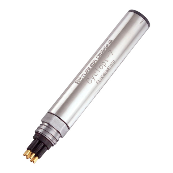
Congratulations on the purchase of your new Cyclops Submersible Sensor. We are committed to customer
satisfaction. If you need assistance, technical specialists are available to answer your questions at 408-749-0994 or
toll-free at 877-316-8049. This Quick Start Guide will help you set up your Cyclops Submersible Sensor and describe
how to take measurements so you can start collecting data as quickly as possible.
How to identify for which fluorophore your Cyclops is configured:
"C" = Chlorophyll
"F" = Fluorescein
"E" = Phycoerythrin
"O" = Crude Oil
"T" = Turbidity
"G" = Refined Fuels
Initial Connections
Initial Connections
Attach the 6-pin female connector to the sensor and connect the wire leads as shown in Figure 1.
Attach the 6-pin female connector to the sensor and connect the wire leads as shown in Figure 1.
Do not connect or ground the Brown and Blue wires at this time.
Do not connect or ground the Brown and Blue wires at this time.
Leaving them disconnected will set the sensor to the X1 gain range.
Leaving them disconnected will set the sensor to the X1 gain range.
Cyclops Pigtail Cable
Cyclops Pigtail Cable
Cyclops Pigtail Cable
Cyclops pins / wires
Cyclops pins / wires
Cyclops pins / wires
Cyclops pins / wires
Cyclops pins / wires
Cyclops pins / wires
Cyclops pins / wires
Cyclops pins / wires
Cyclops pins / wires
Cyclops pins / wires
Cyclops pins / wires
Cyclops pins / wires
Cyclops pins / wires
Cyclops pins / wires
6
6
6
6
6
6
6
6
6
6
6
6
6
6
6
6
6
6
6
6
6
6
6
6
6
6
6
6
6
6
2
2 2
2 2
2 2
2
2 2
2
2
2
2
2
2 2
2 2
2 2
2 2
2
2 2
2 2
2
2
2
2
2 2
2 2
2
2
2
2
2
2
6
6
6
6
6
6
6
6
6
6
6
6
6
6
6
6
6
6
6
6
6
6
6
6
6
6
6
6
6
6
1
1
1
1
1
1
1
1
1
1
1
1
1
1
1
1
1
1
1
1
1
1
1
1
1
1
1
1
1
1
5
5
5 5
5
5 5
5 5
5 5
5
5
5 5
5 5
5 5
5 5
5
5
5
5
5
5 5
5 5
5
5
5
5
5
5
5 5
5 5
5
5
3 3
3 3
3
3
3
3
3 3
3
3
3
3
3
3 3
3 3
3 3
3
3 3
3
3
3 3
3
3
3
3 3
3 3
3
3 3
3
3 3
3
4
4
4
4
4 4
4
4
4 4
4 4
4 4
4
4 4
4
4 4
4 4
4 4
4
4
4
4
4 4
4 4
4
4
4
4
4
4
4 4
4 4
Figure 1
Figure 1
Functional Test Validation
Functional Test Validation
With the Cyclops connected as shown in Figure 1, make the following functional checks:
With the Cyclops connected as shown in Figure 1, make the following functional checks:
•
•
The LED is on
The LED is on
•
•
The multimeter reads >0 VDC
The multimeter reads >0 VDC
•
•
Moving the light source closer to your hand causes the output voltage to increase.
Moving the light source closer to your hand causes the output voltage to increase.
998-0270
"R" = Rhodamine WT
"P" = Phycocyanin
"U" = CDOM / fDOM
"B" = Optical Brighteners
"A" = PTSA
DC Power Supply
DC Power Supply
DC Power Supply
DC Power Supply
12.00
12.00
12.00
12.00
.015
.015
.015
.015
+
+
+
+
PSU Positive Connection
PSU Positive Connection
PSU Positive Connection
(Red)
(Red)
(Red)
Cyclops Pigtail cable holes
Cyclops Pigtail cable holes
Cyclops Pigtail cable holes
Cyclops Pigtail cable holes
Cyclops Pigtail cable holes
Cyclops Pigtail cable holes
Cyclops Pigtail cable holes
Cyclops Pigtail cable holes
Blue
Blue
Blue
2
2
2 2
2 2
6
2
6
2 2
6
2 2
6
2 2
6
2
6
2
6
2 2
6
6
6
2
6
2 2
6
2 2
6
6
6 6
2
6
6
2
2
2
2
6
6 6
6 6
6
2
6 6
2
6 6
2
6 6
2
6 6
2
2
2
2
2
6 6
6
6
1
1
1
1
1
1
1
1
1
1
1
1
1
1
(Tie to Green for
(Tie to Green for
(Tie to Green for
1
1
1
1
1
1
1
1
1
1
1
1
1
1
3
3
3
3
3
3
3
3
3
3
3
3
3
3
5
5
5
5
5
5
5
5
5
5
5
5
5
5
5
5 5
5
5
5 5
5 5
5 5
5 5
5
5 5
5 5
5 5
5
5
3 3
3 3
3
3 3
3
3
3
3
3 3
3 3
3 3
3 3
3
3 3
10X)
10X)
10X)
4
4
4
4
4
4
4 4
4
4
4 4
4 4
4
4
4
4 4
4
4
4
4
4
4
4 4
4
4
4
4 4
4
4
4 4
4
4
4
4
4
4
4
4
4 4
4
4
4
4
www.turnerdesigns.com
Quick Start Guide
-
-
-
-
Supply Ground
Supply Ground
Supply Ground
0 VDC (Black)
0 VDC (Black)
0 VDC (Black)
Signal Output
Signal Output
Signal Output
"+" (White)
"+" (White)
"+" (White)
Brown
Brown
Brown
(Tie to Green for
(Tie to Green for
(Tie to Green for
100X)
100X)
100X)
X1(Low) Gain
X1(Low) Gain
X1(Low) Gain
Leave both wires
Leave both wires
Leave both wires
disconnected
disconnected
disconnected
for Functional Check
for Functional Check
for Functional Check
Revision J
"A" = PTSA
"A" = PTSA
Multimeter
Multimeter
Multimeter
Multimeter
3.52
3.52
3.52
3.52
10 VDC
10 VDC
10 VDC
10 VDC
-
-
-
-
+
+
+
+
Analog Ground
Analog Ground
Analog Ground
"-" (Green)
"-" (Green)
"-" (Green)
Page 1 of 2
Advertisement
Table of Contents

Related Manuals for Turner Designs CYCLOPS 7

Summary of Contents for Turner Designs CYCLOPS 7
- Page 1 Quick Start Guide Congratulations on the purchase of your new Cyclops Submersible Sensor. We are committed to customer satisfaction. If you need assistance, technical specialists are available to answer your questions at 408-749-0994 or toll-free at 877-316-8049. This Quick Start Guide will help you set up your Cyclops Submersible Sensor and describe how to take measurements so you can start collecting data as quickly as possible.
- Page 2 Quick Start Guide Choosing the Right Gain Setting Choosing the Right Gain Setting The gain setting refers to the sensitivity adjustment of the sensor. There are three gain settings – X1, X10 and X100. The gain setting refers to the sensitivity adjustment of the sensor. There are three gain settings – X1, X10 and X100. As the gain increases, the sensitivity increases and the measuring range decreases.
Need help?
Do you have a question about the CYCLOPS 7 and is the answer not in the manual?
Questions and answers