Table of Contents
Advertisement
Quick Links
Advertisement
Table of Contents

Related Manuals for Ethos 4150

Summary of Contents for Ethos 4150
- Page 1 ETHOS 4150 Motor and Phase Rotation Indicator Operating Instructions...
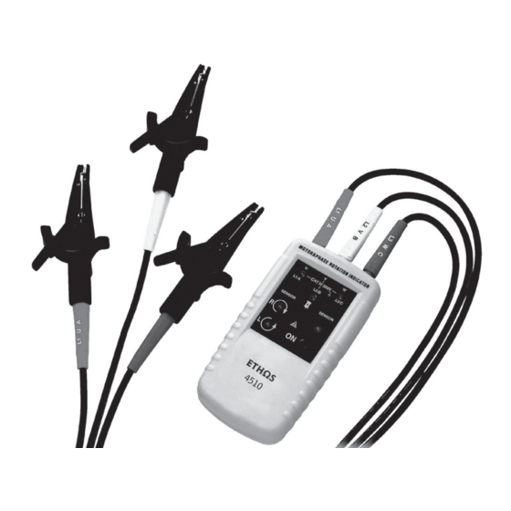
- Page 2 Introduction The Motor and Phase Rotation indicator is a handheld, battery-operated instrument designed to detect the rotary field of three-phase systems determine motor-rotation direction. Symbols The following symbols appear on the Motor and Phase Rotation indicator or in this manual. Table 1.
-
Page 3: Rotation Indicator
Rotation indicator Indicators, buttons, and jacks are shown in Figure 1. Test lead input jack MOTOR&PHASE RO TATIO N INDICATO R L1,L2,L3 Indicators Clockwise Rotation LCD Indicator Counter-Clockwise Rotation LCD Indicator ON/OFF button ON/OFF Indicator Orientation Symbol Figure 1. The Motor and phase Rotation Indicator Using the Motor &... - Page 4 are connected to the corresponding input jacks. 2. Connect the Alligator clips to the other end of the test leads. 3. Connect the Alligator clips to the three mains phases. Press the ON/OFF button. The green ON indicator shows that the instrument is ready for testing.
-
Page 5: Non-Contact Rotary Field Indication
Figure 2. Phase Indication Table (shown on the rear of the Motor and Phase Rotation indicator) Non-contact Rotary Field Indication For non-contact rotary field indication: 1. Disconnect all test leads from the Motor and Phase Rotation indicator. 2. Position the Indicator on the motor so that it is parallel to the length of the motor shaft. - Page 6 for testing. Either the Clockwise or Counter Clockwise Rotary indicator illuminates showing the type of rotary field direction present. Note The indicator will not operate with engines controlled by frequency converters. The bottom of the Motor and Phase Rotation indicator should be oriented towards the drive shaft.
-
Page 7: Determine The Motor Connection
See Table 2 for the minimum motor diameter and number of pole pair to obtain a reliable test result. Table 2. Reliable Motor Test Requirements Min. Angel Between Rotary Number Of Rotary Field (1/min) poles Number of Motorcase at Frequency (HZ) pole pair 16 2/3 3000... -
Page 8: Magnetic Field Detection
3. Connect the alligator clamps to the motor connections, L1 to U, L2 to V, L3 to W. 4. Press the ON/OFF button. The green ON indicator shows that the instrument is ready for testing. 5. Turn the motor shaft half a revolution towards the right. - Page 9 and Phase Rotation indicator to a solenoid valve. A magnetic field is present if either the Clockwise or the Counter Clockwise Rotary indicator illuminate. Note The Motor and Phase Rotation indicator contains alkaline batteries. Do not dispose of these batteries with other solid waste. Used batteries should be disposed of by a qualified recycler or hazardous materials handler.
- Page 10 screw with a screwdriver. 2. Life the battery access lid away from the Motor and Phase Rotation indicator. 3. Observe the battery polarity shown in the battery compartment. 4. Secure the battery access lid back in position with the screw. Unpacking the Motor and Phase Rotation indicator The Motor and Phase Rotation indicator ships...
-
Page 11: Read First: Safety Information
Safety Information C a u ti o n id e n tifi e s c o n d i ti o n s a n d a c tio n s th a t m a y d a m a g e th e D T -9 0 2 W a r n in g id e n ti fie s c o n d itio n s a n d a c tio n s th a t p o s e h a z a r d to th e u s e r . - Page 12 features/protection provided by the equipment. Avoid working alone. Damage leads must be replaced. Do not use the Motor and Phase Rotation indicator if it looks damaged. Be careful when working above 30V ac rms, 42V ac peak and 60V dc. Such voltages pose a shock hazard.
- Page 13 Do not use the Motor and Phase Rotation indicator in a wet environment. cuits Specifications Environmental Operating Temperature 0℃ to +40℃ Operating Altitude 2000 m Pollution Degree Type of protection IP 40 Mechanical Specifications Size (H x W x D): 130mm x 69mm x 32mm. Weight: 130g Humidity...
- Page 14 15% to 80% Safety Specifications Electrical Safety Meets DIN VDE 0411,IEC 61010 DIN, VDE 0413-7, IEC 61557-7/EN 61557-7 Maximum Operating Voltage (Ume) 400 V AC for all ranges Protection Levels CAT lll, 300V Electrical Specifications Battery 9 V alkaline, IEC 6LR61 Current Consumption Max 20 mA Battery life...
- Page 15 Determine Rotary Field Direction Nominal Voltage Rotary Direction 1 to 400 V AC Nominal Voltage phase indirection 120 to 400 V AC Frequency Range (fn) Inspect the test leads for damaged insulation or exposed metal. Check test lead continuity. 2 to 400HZ Test Currents (In per phase) Less than 3.5 m A Non-Contact Rotary Field Indication...
- Page 16 1 to 400 V AC Nominal Test Currents (In per phase) Less than 3.5 m A Frequency Range (fn) 2 to 400 HZ...
- Page 17 Distributed by MTi Unit 12, Access 18, Kings Weston Lane, Bristol BS11 8HT Tel: 0117 938 6400 Fax: 0117 923 5374 Email: enquiries.ethos@adivision.co.uk Web: www.ethos-instruments.co.uk...
Need help?
Do you have a question about the 4150 and is the answer not in the manual?
Questions and answers
probe stays lit after inserting new battries on my 4150 continity & voltage Test probe