
Related Manuals for Harman AMX DXLINK DX-TX-DWP-4K

Summary of Contents for Harman AMX DXLINK DX-TX-DWP-4K
- Page 1 H A RDW A RE REF EREN CE M A N UA L DX L I N K ™ TW I STED PA I R 4 K TRA N S M I TTE RS / R E C E I VE RS DX -TX- DWP- 4K , DX- RX -4 K...
- Page 2 IMPORTANT SAFETY INSTRUCTIONS READ these instructions. KEEP these instructions. HEED all warnings. FOLLOW all instructions. DO NOT use this apparatus near water. CLEAN ONLY with dry cloth. DO NOT block any ventilation openings. Install in accordance with the manufacturer's instructions. DO NOT install near any heat sources such as radiators, heat registers, stoves, or other apparatus (including amplifiers) that produce heat.
- Page 3 WARNING: This product is intended to be operated ONLY from the voltages listed on the back panel or the recommended, or included, power supply of the product. Operation from other voltages other than those indicated may cause irreversible damage to the product and void the products warranty.
-
Page 4: Table Of Contents
CONTENTS CONTENTS Product Overview and Specifications ................7 Applicability Notice ........................7 Product Notes..........................7 Product Compatibility Tables ...................... 8 DXLink Transmitter and Receiver Features................. 9 Common Applications ......................... 9 Transmitters ..........................10 Receivers ........................... 11 Common Features/Functionality ....................13 Quick Reference Tables for Modes .................... 14 Installation and Setup ....................20 Site Recommendations ...................... - Page 5 CONTENTS NetLinx Programming of DXLink Receivers ..............47 Overview ............................ 47 Device Numbering and Ports..................... 47 CHANNELs..........................48 DXLink Receiver Video SEND_COMMANDs................. 49 DXLink Receiver Audio SEND_COMMANDs ................52 DXLink Receiver IR SEND_COMMANDs ..................53 DXLink Receiver Serial SEND_COMMANDs ................56 DXLink Receiver USB SEND_COMMANDs...................
- Page 6 CONTENTS Appendix D – Cable Details and Pinout Info .............80 Overview ............................ 80 HDMI Connector Cable Pinout....................80 DVI Pinout for DVI-to-HDMI Cable Adapter................81 Appendix E - Supported Output Resolutions ............82 ICSP Settable Output Resolutions..................... 82 Digital Video Output Resolution Support .................. 83 Appendix F - Ground Wire Attachment ..............87 Applicability..........................
-
Page 7: Product Overview And Specifications
Product Overview and Specifications Product Overview and Specif ications Applicability Notice The information in this manual applies to the DXLink 4K Decor Style Wallplate Transmitter and the DXLink 4K HDMI Receiver Module listed in the table below. In this manual, these products will be referred to as the 4K HDMI Wallplate TX and the 4K RX. When referring to transmitter units, the term Transmitters is used. -
Page 8: Product Compatibility Tables
Product Overview and Specifications Product Compatibility Tables The 4K HDMI Wallplate TX and 4K RX are compatible with the products listed in the three tables following. NOTE: DXLink Twisted Pair 4K Transmitters and Receivers are primarily intended for use with 4K signals. These units can, however, be used with DXLink Twisted Pair equipment. -
Page 9: Dxlink Transmitter And Receiver Features
Product Overview and Specifications DXLink Transmitter and Receiver Features NOTE: Wallplate Transmitters have a limited set of features (i.e., no S/PDIF, IR, or serial ports). Supports transport of 4K and UHD format signals Incorporates HDMI® technology HDCP 1.4 compatible ... -
Page 10: Transmitters
Product Overview and Specifications Transmitters DXLink 4K HDMI Wallplate TX (DX-TX-DWP-4K) Front View DXLink LED HDCP LED HDMI Input Cover plate screw hole Back box screw hole 4K HDMI Wallplate TX front view (before customer provided standard decor style front cover plate is attached) FIG. -
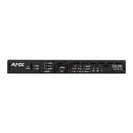
Page 11: Receivers
Product Overview and Specifications Receivers NOTE: If a DVI-D signal is used (via a DVI-to-HDMI cable adapter), the advanced audio support from HDMI will not be available. DXLink Receivers Front View Video and Audio LEDs NetLinx LEDs USB LED IR LEDs Power LED Program port ID Pushbutton... - Page 12 Product Overview and Specifications Receiver Rear View Power jack USB port Stereo Audio Out connector DXLink input connector Ground screw RS-232 port HDMI Out connector ICS LAN 10/100 IR ports DXLink Receiver rear view (DX-RX-4K shown) FIG. 4 The following components are located on the rear of Receivers (left to right): Power Jack –...
-
Page 13: Common Features/Functionality
Product Overview and Specifications Common Features/Functionality This section covers the DIP switches, the USB port, and HDCP compliance. DIP Switches The following DIP switch settings do not in any way affect the functionality of the DX-TX-DWP-4K and are not applicable when configuring a DX-RX-4K for use with an Enova DGX in Auto-setup Mode. -
Page 14: Quick Reference Tables For Modes
Product Overview and Specifications Select the Power Management tab and click “Allow this device to wake the computer.” Select this option Click OK. Repeat steps for HID mouse (in the Device Manager dialog box, expand “Mice”). HID Devices HID Devices A list is available of HID devices which have been tested and found to be working well with the latest firmware (see “DXLink - HID supported Devices”... - Page 15 Product Overview and Specifications Quick Reference Table – Modes for Handling Addressing/Networking (DX_RX-4K only) Mode Description IP Addressing IP Addressing Modes refer to network connection settings. By default, all network connection settings are turned OFF. Modes Static IP Mode: • This mode configures the network connection to one stable IP address the device will use continuously. DHCP Mode: •...
- Page 16 Product Overview and Specifications DXLink Transmitter and Receiver Specif ications The specifications in the table below apply to the following Transmitters and Receivers: FG1010-330-BL – DX-TX-DWP-4K (US), Black FG1010-330-WH – DX-TX-DWP-4K (US), White FG1010-510 – DX-RX-4K General Specif ications Parameter Value Approvals...
- Page 17 Product Overview and Specifications General Specif ications Twisted pair Cable Twisted Pair Cable Type • Shielded Cat6A or Cat7 Specs NOTE: For more details and helpful cabling information, reference the white paper titled “Cabling for Success with DXLink” available at www.amx.com or contact your AMX representative.
- Page 18 Product Overview and Specifications USB (HID) Keyboard and Mouse Specif ications Parameter Value DX-RX-4K • (1) USB Type A connector (“Device”) • Connect a keyboard and mouse and send commands to a PC connected to a DXLink Transmitter with compatible USB connector. NOTE: A list of HID devices which have been tested and found to be working well with the latest f irmware is available (see “DXLink - HID supported Devices”...
- Page 19 Product Overview and Specifications HDMI Specif ications – Transmitters only Parameter Value Input Signal Type • HDMI • DVI-D (Single Link with a DVI-to-HDMI cable adapter) • DisplayPort ++ (input only with HDMI cable adapter) DDC/EDID Support • The HDMI EDID in point to point mode is passed up from the sink device. •...
-
Page 20: Installation And Setup
Installation and Setup Installation and Setup Site Recommendations When placing DXLink Transmitters and Receivers in an installation, follow the recommendations and precautions in this section to reduce potential setup and operation hazards. Environment Choose a clean, dust free, (preferably) air-conditioned location. Avoid areas with direct sunlight, heat sources, or high levels of EMI (Electromagnetic Interference). -
Page 21: Setup Information
Installation and Setup Setup Information IMPORTANT: The setup information in this manual applies to TXs and RXs in an Enova DGX 100 Series system with the auto-setup feature disabled. When the auto-setup feature for an Enova DGX 100 Series Switcher is enabled (the default), DXLink equipment is automatically discovered and connected to the switcher using a private network hosted by the integrated Master (for complete information, see the “Hardware Reference Manual –... - Page 22 Installation and Setup Options for System Setup with Enova DGX DXLink Boards The following table contains options for using DXLink Transmitters and Receivers in conjunction with DXLink Twisted Pair Input and Output Boards in an Enova DGX 100 Series Digital Media Switcher. System Setup Options –...
- Page 23 Installation and Setup Extender Mode (Standalone): Example of Typical System Setup A Transmitter and Receiver standalone pair can also work together as an extender solution for transmission of HDMI over twisted pair cable up to 262 feet (80 m). The standalone setup supports DVI-D signals with the use of a DVI-to-HDMI cable adapter. In systems with a Wallplate Transmitter, power can be provided to the units via the DXLink line by connecting a DXLink power injector to the Wallplate and using either the desktop power supply or another DXLink power injector with the Receiver.
- Page 24 Installation and Setup Foregoing Power Supply Redundancy Depending on particular Enova DGX input and output board configurations, operating over the redundant power supply level may be necessary on a permanent basis for some installations. While foregoing the benefits associated with a redundant power supply should be understood, operating without redundancy is in no way detrimental to the system, as long as both power supplies are operational.
- Page 25 Installation and Setup NetLinx Binding of DXLink Receiver Modules with an Enova DGX Switcher IMPORTANT: The information in this section does not pertain to the 4K HDMI Wallplate TX as the device does not communicate with or receive control from NetLinx Studio. NOTE: If a DXLink module has been conf igured for auto-setup mode and then auto-setup mode has been disabled, the unit may take longer to appear in NetLinx Studio than expected (1-2 minutes).
- Page 26 Installation and Setup Setting DIP Switch #2 to Set the DXLink Mode #2 Toggle can be set to automatically or manually select the DXLink Mode (to either Extender or Endpoint) for a given DXLink Module. Default state for #2 Toggle (OFF) is auto selection of DXLink Mode based on connection to another device. When it’s ON, the default is Endpoint Mode (used for Master controlled serial/IR data transfer).
- Page 27 Installation and Setup Scenarios / DIP Switch Settings Table The table below contains the most common scenarios for setting up DXLink Modules as a standalone pair or with other equipment. Find the scenario in the table that you want to use and then set the DIP switches accordingly. A detailed explanation of functions for each toggle is provided on previous pages.
- Page 28 Installation and Setup DXLink Transmitter and Receiver Ground Wire Attachment Attaching ground wires to DXLink Transmitters and Receivers is only required when instructed to do so by Technical Support or an electrical technician. For instructions on attaching a ground wire, see page 87. Important Twisted Pair Cabling Requirements and Recommendations The following requirements and recommendations apply to cabling DXLink (RJ-45) connectors: DXLink cable runs require shielded category cable (STP) of Cat6a or Cat7.
- Page 29 Installation and Setup DXLink Connector LEDs DXLink Connector The following information applies to the LEDs located on the DXLink (RJ-45) connectors on the rear of DXLink units. LEDs Yellow: On – Authenticated HDCP (handshaking has occurred successfully) Flashing – Video active; no HDCP ...
-
Page 30: Wallplate Transmitters - Attaching Signal/Transport Cables
Installation and Setup Wallplate Transmitters – Attaching Signal/Transport Cables To attach signal and transport cables to a Wallplate Transmitter: Install standard US single-gang back box. Attach a twisted pair cable from the DXLink Input Board on the switcher to the DXLink (RJ-45) connector on the rear of the unit. -
Page 31: Receiver Modules - Applying Power
Installation and Setup Receiver Modules – Applying Power IMPORTANT: If desktop power is used to power the Receiver, only the provided desktop power supply should be used and it must not be altered in any way. Remote power can only be provided via the switcher, PDXL-2 (FG1090-170), or PS-POE-AT-TC (FG423-84). IMPORTANT: The “Important Power Considerations for Enova DGX Systems”... -
Page 32: Serial Data Transfer And Ir Flow Control
Installation and Setup Serial Data Transfer and IR Flow Control IMPORTANT: The information in this section does not pertain to the 4K HDMI Wallplate TX as the device does not use serial or IR communication (for information on DXLink Transmitters that are compatible with the DXLink Twisted Pair 4K HDMI Receiver, see the “DXLink Compatibility Appendix”... -
Page 33: Optional: Ir Control On Dxlink Modules
Installation and Setup Optional: IR Control on DXLink Modules IMPORTANT: The information in this section does not pertain to the 4K HDMI Wallplate TX as the device does not use serial or IR communication (for information on DXLink Transmitters that are compatible with the DXLink Twisted Pair 4K HDMI Receiver, see the “DXLink Compatibility Appendix”... -
Page 34: Id Pushbutton Functions
Installation and Setup ID Pushbutton Functions The ID Pushbutton is located on the right front of the Receiver Module. The ID Pushbutton can be used to perform four types of initial configuration settings: Toggle between DHCP and static IP addressing ... -
Page 35: Detailed Netlinx (Link/Act And Status) Led Behavior
Installation and Setup Detailed NetLinx (Link/Act and Status) LED Behavior The tables below provide detailed descriptions of all blink patterns for the NetLinx Link/Act and Status LEDs on the front of the Receiver Modules. NOTE: “Light show” refers to the back-and-forth scanning pattern of the LEDs on DXLink Modules. Module Operational State as Indicated by LEDs To determine the operational state (normal boot) of a DXLink Module by its LEDs, check both the Link/Act and Status LED columns. -
Page 36: Dxlink 4K Tx/Rx In A Multiple-Stage Switching System
Installation and Setup DXLink 4K TX/RX in a Multiple-Stage Switching System When switching systems with DXLink Technology support (e.g., Enova DGX 100 Series Digital Media Switchers) are connected via their DXLink ports, DXLink Transmitters and Receivers can be used to extend the video and audio transport. IMPORTANT: This section does not refer to the linking of enclosures from CPU to CPU, which is not supported in Enova DGX 100 Series Digital Media Switchers. -
Page 37: Network Configuration
Network Configuration Network Conf iguration Overview IMPORTANT: The information in this Chapter does not pertain to the 4K HDMI Wallplate TX as the device does not provide TCP/IP communication to a network, does not have an IP address to conf igure, and does not require resettable factory settings. IMPORTANT: If DXLink Modules are connected to an Enova DGX 100 Series Switcher using auto-setup, see the “Hardware Reference Manual –... -
Page 38: Tcp/Ip Address Configuration
Network Configuration TCP/IP Address Conf iguration DXLink Modules support IPV4 network addresses, gateway addresses, DNS server addresses, and network names. They also support NDP (NetLinx Discovery Protocol) capabilities as well as IP discovery via NetLinx Studio. NOTE: NDP is a device discovery method used by NetLinx Masters. With NDP Beacon enabled, the Master will transmit NDP Beacons for AMX’s proprietary device discovery. -
Page 39: Factory Default Parameters
Network Configuration Factory Default Parameters Factory Default Parameters Parameter Value MAC Address As set in factory Serial Number As set in factory Ethernet Mode Auto (i.e., speed, duplex, both, auto) IP Addressing Mode DHCP IP Address (for static mode) 192.168.1.2 Netmask (for static mode) 255.255.255.0 Gateway (for static mode) -
Page 40: Using The Id Pushbutton
Network Configuration Using the ID Pushbutton The ID Pushbutton is located on the right front of DXLink Modules. ID Pushbutton ID Pushbutton on Module (DX-RX-4K shown) FIG. 23 The ID Pushbutton can be used to perform four types of initial configuration settings: Toggle between DHCP and static IP addressing (see below) ... - Page 41 Network Configuration In the ID Mode section, enter the Device and System numbers that you want assigned to the device in the appropriate text boxes. Click Start Identify Mode to place the named system in ID Mode. The button changes to “Cancel Identify Mode” (click to cancel ID Mode). The text box below the button displays a “Waiting...Press Cancel to Quit”...
- Page 42 Network Configuration TIP: In the following procedure – if you start a press and hold sequence with the ID Pushbutton and then decide not to change the settings, before you release the ID Pushbutton remove power from the unit to abort the procedure (remember, power can be applied via the external power supply or over DXLink, so one or both sources of power may need to be removed).
-
Page 43: Irl File Transfers
IRL File Transfers IRL File Transfers Overview IMPORTANT: The information in this Chapter does not pertain to any of the 4K HDMI Wallplate TX as the device does not provide IR communication ports. The NetLinx Studio software application (available for free download from www.amx.com) provides the ability to transfer IR Library files to NetLinx devices such as DXLink Modules. -
Page 44: Transferring Irl Files
IRL File Transfers Click OK. Determine the Device Number assigned to the target Module when it was bound. For the Device Number location, see FIG. 24 on the previous page. The Module is ready for the IRL file transfer (see page 44). Transferring IRL Files The File Transfer tool in NetLinx Studio is used to map IRL files to DXLink Modules. - Page 45 IRL File Transfers Select the type of file (in this case, IRL/IRV Files) that you want to add to the File list for transfer. Click Add. A standard Open dialog box opens with the Files of type selection set to IR Code files (*.IRL/*.IRV). Locate and select the IRL file that you want to add.
- Page 46 IRL File Transfers Additional Documentation For additional information on using NetLinx Studio, refer to the WebConsole & Programming Guide – NX-Series Controllers (available at www.amx.com). Additional IRL Information ICSLan powered devices (such as the DXLink Modules) are not capable of having their IRL files received via the File Transfer dialog box, nor do they support the SEND_COMMAND: LOADIRL.
-
Page 47: Netlinx Programming Of Dxlink Receivers
NetLinx Programming of DXLink Receivers NetLinx Programming of DXLink Receivers Overview IMPORTANT: The information in this Chapter does not pertain to the 4K HDMI Wallplate TX as the device does not communicate with or receive control from NetLinx Studio. NOTE: Transmitters referenced in this chapter must meet the compatibility requirements described in the “DXLink Compatibility Appendix”... -
Page 48: Channels
NetLinx Programming of DXLink Receivers In NetLinx Studio’s OnLine Tree, the DXLink Receiver Module displays its ports. Integrated Master Enova DGX 3200 Device number DXLink Receiver DXLink Receiver Port 1 - Serial ICSP (COM) Port 2 - Not used Port 3 - IR Output (TX) Port 4 - IR Input (RX) Ports 1-7 on DXLink Receiver Port 5 - USB (HID) device data... -
Page 49: Dxlink Receiver Video Send_Commands
NetLinx Programming of DXLink Receivers DXLink Receiver Video SEND_COMMANDs DXLink Receiver Video SEND_COMMANDs are sent to Port 6. NOTE: Asynchronous notif ications are not available for the Receivers via NetLinx Studio (or Telnet). Video SEND_COMMANDs (Receivers) Command Description ?VIDOUT_ASPECT_RATIO Syntax: Requests the aspect ratio preference SEND_COMMAND <DEV>,"'?VIDOUT_ASPECT_RATIO'"... - Page 50 NetLinx Programming of DXLink Receivers Video SEND_COMMANDs (Receivers) ?VIDOUT_MUTE Syntax: Requests the setting for the Mute SEND_COMMAND <DEV>,"'?VIDOUT_MUTE'" Example: preference applied to the image from the Receiver (Enable or Disable). SEND_COMMAND dvRX,"'?VIDOUT_MUTE'" Returns a COMMAND of the form: VIDOUT_MUTE-<ENABLE|DISABLE> VIDOUT_MUTE Syntax: Sets the Mute preference of the SEND_COMMAND <DEV>,"'VIDOUT_MUTE-<ENABLE|DISABLE>'"...
- Page 51 NetLinx Programming of DXLink Receivers Video SEND_COMMANDs (Receivers) VIDOUT_RES_REF Syntax: Sets the resolution and refresh rate SEND_COMMAND <DEV>,"'VIDOUT_RES_REF-<horizontal>x<vertical>,<rate>'" Valid responses: of the video through the Receiver and • horizontal = An integer value representing the horizontal. also sets the Scaling Mode to MANUAL.
-
Page 52: Dxlink Receiver Audio Send_Commands
NetLinx Programming of DXLink Receivers Aspect Ratio Options Stretch (to fit) – This option (default) scales the video to full screen size in both horizontal and vertical directions regardless of the input aspect ratio. No data is cropped. However, the image may be distorted as needed to fill the screen. When Stretch is selected, black bars are not added by the scaler. -
Page 53: Dxlink Receiver Ir Send_Commands
NetLinx Programming of DXLink Receivers DXLink Receiver IR SEND_COMMANDs DXLink Receiver Module IR CHANNELS and SEND_COMMANDs are sent to Port 3 (IR output). IR CHANNELs Channel Function 1-255 Generate the IR or serial command assigned to that channel. IR SEND_COMMANDs IR SEND_COMMANDs (Receivers) Command Description... - Page 54 NetLinx Programming of DXLink Receivers IR SEND_COMMANDs (Receivers) CTON This command sets the pulse length for each pulse generated by the 'CH' (see previous page) or 'XCH' (see next page) Send Commands in tenth of a second increments. Sets the total time of IR pulses Syntax: transmitted and is stored in non- volatile memory.
- Page 55 NetLinx Programming of DXLink Receivers IR SEND_COMMANDs (Receivers) Syntax: Transmit IR codes. SEND_COMMAND <DEV>,"'XCH <channel>'" Valid response: channel = 0 to 999. NOTE: For detailed usage examples, refer to the 'XCHM' command. XCHM Syntax: Changes the IR output pattern for SEND_COMMAND <DEV>,"'XCHM <extended channel mode>'"...
-
Page 56: Dxlink Receiver Serial Send_Commands
NetLinx Programming of DXLink Receivers DXLink Receiver Serial SEND_COMMANDs DXLink Module SERIAL SEND_COMMANDs are sent to Port 1. Serial SEND_COMMANDs (Receivers) Command Description B9MOFF This command works in conjunction with the 'B9MON' command. • Disables 9-bit in 232 mode. Set the port’s communication parameters for stop and data bits •... -
Page 57: Dxlink Receiver Usb Send_Commands
NetLinx Programming of DXLink Receivers Serial SEND_COMMANDs (Receivers) RXON This command is automatically sent by the Master when a 'CREATE_BUFFER' program instruction is executed. Start transmitting received Syntax: characters to the Master. Enables sending incoming received SEND_COMMAND <DEV>,"'RXON'" Example: characters to the Master. SEND_COMMAND dvRXRS232,"'RXON'"... -
Page 58: Common Dxlink Receiver Send_Commands
NetLinx Programming of DXLink Receivers Common DXLink Receiver SEND_COMMANDs Common NetLinx SEND_COMMANDs for DXLink Receivers are provided in the following table. These commands can be sent to any port (the #3 Toggle must be set to ON). Common NetLinx SEND_COMMANDs (Receivers) Command Description ?FWVERSION... -
Page 59: Dxlink System Send_Commands
NetLinx Programming of DXLink Receivers DXLink System SEND_COMMANDs DXLink System SEND_COMMANDs can be sent to any port on the Receiver. DXLink System SEND_COMMANDs (Receivers) Command Description ?DXLINK Syntax: Requests the current mode for the SEND_COMMAND <DEV>,"'?DXLINK'" Example: Receiver. SEND_COMMAND dvRX,"'?DXLINK'" Returns a COMMAND of the form: DXLINK-<DXLINK-EXTENDER/DXLINK-ENDPOINT>... -
Page 60: Send_String Escape Sequences
NetLinx Programming of DXLink Receivers SEND_STRING Escape Sequences DXLink Modules support several special SEND_STRING escape sequences. If any of the character combinations listed below are found anywhere within a SEND_STRING program instruction, they will be treated as a command and not the literal characters. Use the ESCSEQON and ESCSEQOFF NetLinx SEND_COMMANDS to control whether these are active or not. -
Page 61: Troubleshooting
Troubleshooting Troubleshooting Overview The troubleshooting suggestions/strategies provided apply to the Transmitters and Receivers, unless otherwise noted. Five potential types of issues are covered in this chapter: Basic troubleshooting Determining HDCP compliance Power DXLink connections Network setup ... -
Page 62: Dxlink Connection Issues
Troubleshooting DXLink Connection Issues One method for determining DXLink connection issues is to compare the pattern of the green and yellow DXLink LEDs on the Receiver Module against the tables below and then check the suggested items in the Troubleshooting column in the second table. DXLink LED Patterns When Connection is Working as Expected Check the status of the green and yellow DXLink LEDs (on rear of the modules) against the following table to determine the status of the video signal over the DXLink line. -
Page 63: Technical Support
Troubleshooting Establish a Telnet connection to the DXLink Module and set up the network parameters using the following three commands: SET IP SET CONNECTION SET DEVICE Enter REBOOT. Reset the DIP switches to configure the DXLink Module for the specific type of system setup being used (see the “Common Scenarios”... -
Page 64: Appendix A - Upgrading The Firmware
Appendix A - Upgrading the Firmware Appendix A - Upgrading the Firmware Overview IMPORTANT: The information in this Chapter does not pertain to the 4K HDMI Wallplate TX as the device does not contain upgradeable f irmware. The NetLinx Studio software application (available for free download from www.amx.com) provides the ability to transfer KIT files to NetLinx devices such as DXLink Receivers. -
Page 65: Preparing For Kit File Transfers
Appendix A - Upgrading the Firmware Preparing for KIT File Transfers NOTE: The DX-TX-DWP-4K does not require any special steps to prepare for upgrades. This section only applies to the DX-RX-4K. To prepare for KIT f ile transfers: Check to be sure #3 Toggle on the bottom of the Receiver is set to ON. Verify that you have the latest version of NetLinx Studio on your PC. -
Page 66: Transferring Kit Files
Appendix A - Upgrading the Firmware Transferring KIT Files The system will be non-operational during the upgrade procedure below. The Firmware Transfers tool in NetLinx Studio is used to map KIT files to DXLink 4K Receivers. The instructions below assume that the preparations on the previous pages have been completed. -
Page 67: Appendix B - Telnet (Terminal) Commands
Appendix B - Telnet (Terminal) Commands Appendix B - Telnet (Terminal) Commands Establishing a Terminal Connection Via Telnet IMPORTANT: The information in this Appendix does not pertain to the 4K HDMI Wallplate TX as the device does not communicate with or receive control from a terminal connection. -
Page 68: Telnet Username And Password
Appendix B - Telnet (Terminal) Commands To establish a terminal connection via NetLinx Studio: In the Online Tree, select the DXLink unit and right-click to access the short-cut menu. Select Launch Telnet Window via NetLinx Studio. The Telnet window opens and the welcome banner appears. At the prompt (>), type the Telnet command and press Enter. -
Page 69: Telnet Commands
Appendix B - Telnet (Terminal) Commands Setting a Telnet Username and Password To set a Telnet username and password: Establish a terminal connection via Telnet (see page 67). Type Set Telnet Username, and press Enter. The program will prompt you to enter a new Telnet username; enter a username and press Enter. The program will indicate that the username is being stored. - Page 70 Appendix B - Telnet (Terminal) Commands Telnet Commands GET CONFIG Displays the current connection settings. Example: >get config Device number: 7010 Connection Settings -------------------------------- Mode: System Number: 2155 Master IP/URL: 192.168.43.83 Master Port: 1319 Username: Password: IP Settings -------------------------------- HostName: DXL-RX-36d0110 Type: DHCP...
- Page 71 Appendix B - Telnet (Terminal) Commands Telnet Commands GET IP Displays the IP configuration of a device. The device displays its D:P:S, Host Name, Type (DHCP or Static), IP Address, Subnet Mask, Gateway IP, and MAC Address. Example: >GET IP HostName DXL-RX-36d0110 Type...
- Page 72 Appendix B - Telnet (Terminal) Commands Telnet Commands SET CONNECTION Sets the Master connection settings interactively, allowing the user to specify the mode (for descriptions of SET CONNECTION various connection modes, see page 14). Telnet Command • If the mode is TCP or UDP, the Master URL and port number can be specified as well. •...
- Page 73 Appendix B - Telnet (Terminal) Commands Telnet Commands SET IP Sets the IP configuration of a specified device. Enter a Host Name, Type (DHCP or Fixed), IP Address, Subnet Mask, and Gateway IP Address. IMPORTANT: Host Names may only contain ASCII letters “a” through “z” (not case-sensitive), digits “0”...
-
Page 74: Master Connection Modes
Appendix B - Telnet (Terminal) Commands Telnet Commands SHOW LOG Displays the message log. Syntax: SHOW LOG <start> Specifies the message number to start displaying. SHOW LOG <all> SHOW LOG Displays all messages. SHOW VS100 STATS Displays DXLink transport information (MSE values, length, etc.). Master Connection Modes The mode of communication used for connection to the Master is specified via the SET CONNECTION Telnet command (see page 72). -
Page 75: Notes On Specific Telnet Clients
Appendix B - Telnet (Terminal) Commands Notes on Specif ic Telnet Clients Telnet and terminal clients exhibit different behaviors in some situations. This section states some of the known anomalies. Windows Client Programs ® Anomalies occur when using a Windows client if you are not typing standard ASCII characters (i.e., using the keypad and the Alt key to enter decimal codes). -
Page 76: Appendix C - Virtual Netlinx Master
Appendix C - Virtual NetLinx Master Appendix C - Virtual NetLinx Master Overview Virtual NetLinx Master (Masterless) IMPORTANT: The information in this Appendix does not pertain to the 4K HDMI Wallplate TX as the device does not communicate with or receive control from NetLinx Studio. A Virtual NetLinx Master can be created using your PC, which allows NetLinx Studio to facilitate direct file transfers to a DXLink Receiver when a Master is not available. - Page 77 Appendix C - Virtual NetLinx Master Right-click on Local Area Connection and select Properties. The Local Area Connection Properties dialog box opens. From the list of “This connection uses the following items” (see previous step), highlight Internet Protocol Version 4 (TCP/IPv4) and click Properties.
-
Page 78: Creating A Virtual Master
Appendix C - Virtual NetLinx Master Creating a Virtual Master To create a Virtual Master in NetLinx Studio: Open NetLinx Studio. From the Settings menu, select Workplace Communication Settings. Click to open the Communication Settings dialog box Click the Default Settings button. The Communication Settings dialog box opens. -
Page 79: Preparing A Dxlink Unit To Work With A Virtual Master
Appendix C - Virtual NetLinx Master Preparing a DXLink Unit to Work with a Virtual Master Preparing the DXLink Receiver to work with a Virtual Master requires placing the unit in Static IP Mode, assigning it a device ID, and setting the connection type to TCP. -
Page 80: Appendix D - Cable Details And Pinout Info
Appendix D – Cable Details and Pinout Info Appendix D – Cable Details and Pinout Info Overview Both DXLink Transmitters and Receivers have connectors for HDMI. HDMI Connector Cable Pinout HDMI connectors are found on all DXLink units. These connectors are used to pass HDMI or DVI-D signals (using a DVI-to-HDMI cable adapter) from a source device to a DXLink Transmitter or from a DXLink Receiver to a destination device. -
Page 81: Dvi Pinout For Dvi-To-Hdmi Cable Adapter
Appendix D – Cable Details and Pinout Info DVI Pinout for DVI-to-HDMI Cable Adapter The pinout in FIG. 28 is for DVI-to-HDMI cable adapters which can be used with the modules when a DVI-I signal is required DVI pinout for DVI-to-HDMI cable adapter FIG. -
Page 82: Appendix E - Supported Output Resolutions
Appendix E - Supported Output Resolutions Appendix E - Supported Output Resolutions ICSP Settable Output Resolutions The resolutions in the following table are supported on the Receivers and can be set using a SEND_COMMAND. The horizontal/ vertical/refresh information from the Resolution Name (in the first column) can be entered in a SEND_COMMAND command (VIDOUT_RES_REF) to specify scaling parameters for the Receiver. -
Page 83: Digital Video Output Resolution Support
Appendix E - Supported Output Resolutions Digital Video Output Resolution Support IMPORTANT: The resolutions and timings in the list below can only be set via the Enova DGX Switcher when the DXLink Receiver is being used directly from a DXLink output board. CTA (RGB Color Space): 640x480p,59Hz 720x480p,59/60Hz... - Page 84 Appendix E - Supported Output Resolutions CVR (RGB Color Space): IMPORTANT: The resolutions and timings in the list below can only be set via the Enova DGX Switcher when the DXLink Receiver is being used directly from a DXLink output board. 768x480,60Hz 800x600,60Hz 800x600,120Hz...
- Page 85 Appendix E - Supported Output Resolutions CVT (RGB Color Space): IMPORTANT: The resolutions and timings in the list below can only be set via the Enova DGX Switcher when the DXLink Receiver is being used directly from a DXLink output board. 1280x800,50Hz 640x360,85Hz 1280x800,75Hz...
- Page 86 Appendix E - Supported Output Resolutions DMR (RGB Color Space): IMPORTANT: The resolutions and timings in the list below can only be set via the Enova DGX Switcher when the DXLink Receiver is being used directly from a DXLink output board. 1280x800,60Hz 1366x768,60Hz 1600x900,60Hz...
-
Page 87: Appendix F - Ground Wire Attachment
Appendix F - Ground Wire Attachment Appendix F - Ground Wire Attachment Applicability If the system is experiencing problems with delivery of DXLink signals to/from an Enova DGX Digital Media Switcher, adding a ground wire from the TX/RX to the switcher may improve performance. The problem is likely caused by the use of a single phase powered system that does not provide an earth ground for a source or destination's chassis and shields. - Page 88 Appendix F - Ground Wire Attachment Ensure the ground wire is positioned so that it does not interfere with any of the connectors. Correctly positioned ground wire Position ground wire away from connectors FIG. 30 Attach the ground wire to a common earthed ground (see “Attaching a Ground Wire to a Common Earthed Ground” on previous page).
-
Page 89: Appendix G - Dxlink Compatibility
Appendix G - DXLink Compatibility Appendix G - DXLink Compatibility Overview While DXLink Twisted Pair 4K hardware is intended for primary use with other DXLink Twisted Pair 4K hardware (full capability compatibility), it is also compatible with DXLink Twisted Pair hardware. When DXLink Twisted Pair 4K is used in conjunction with DXLink Twisted Pair hardware, Input and Output signal support matches the lowest common denominator (e.g., if you want to use the DX-TX with the DX-RX-4K, the DX-RX-4K will behave exactly like a DX-RX). - Page 90 Appendix G - DXLink Compatibility DXLink Twisted Pair 4K and DXLink Twisted Pair Hardware Capabilities The following tables display hardware capability differences and similarities between DXLink Twisted Pair 4K and DXLink Twisted Pair Transmitters and between DXLink Twisted Pair 4K and DXLink Twisted Pair Receivers. Transmitter Hardware Capabilities DX-TX DX-TX-WP...
- Page 91 © 2016 Harman. All rights reserved. SmartScale, NetLinx, Enova, AMX, AV FOR AN IT WORLD, and HARMAN, and Last Revised: their respective logos are registered trademarks of HARMAN. Any other company or brand name referenced may 6/1/2016 be trademarks/registered trademarks of their respective companies.
Need help?
Do you have a question about the AMX DXLINK DX-TX-DWP-4K and is the answer not in the manual?
Questions and answers