
Related Manuals for Sigma 700 Series


Summary of Contents for Sigma 700 Series
- Page 1 DIVERSIFIED HEAT TRANSFER SERIES 700 ‘WATER HEATER’ CONTROLLER INSTRUCTION MANUAL VISIT OUR WEBSITE SIGMACONTROLS.COM SERIES 700 DHT WATER HEATER MANUAL 042314...
-
Page 2: Table Of Contents
- 2 - TABLE OF CONTENTS INTRODUCTION……………………………………… Ordering Information Specifications Features WIRING………………………………………………… Dwg # 13-256 Analog Input Analog Output Digital Input Digital Output PROGRAMMING AND INITIAL SETUP…………….. Input Range Selection Terminal Block Detail Initial Setup & Programming Overview/Key Description PROGRAMMING RECORD SHEET…………………. RETURN AUTHORIZATION FORM…………………... -
Page 3: Introduction
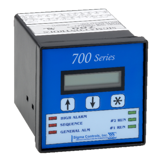
- 3 - INTRODUCTION: The Sigma 700 Series (Water Heater Controller) is a microprocessor based, state of the art, device offering unmatched performance and full user configurability. The 700 Series is used with a temperature transmitter whose output signal is compatible with 4/20MA. - Page 4 - 4 - 3 USER KEYS: Up, Down, Enter ACCURACY: 0.1% of calibrated span LOCKOUT: User password, user configurable INPUT IMPEDANCE: Voltage 100K, current 100 OHMS POWER: 24VDC std (120VAC optional) ENVIRONMENTAL: Operating, 0-65° C Storage, -40° -80° C R.H., 0-90% non condensing ENCLOSURE: ¼...
-
Page 5: Features
- 5 - PROGRAMMING: Menu based, all parameters and setpoints are user configurable via menu prompts and user keys. The preconfigured screens and ‘pull down’ sub menus with English prompts assures rapid setup and commissioning. 1 YEAR WARRANTY OPTIONS: I/O board includes an additional 110VAC power supply, 1 AI, 1 AO, 8 relay drivers ... -
Page 6: Wiring
- 6 - WIRING DETAIL Inputs/Output see Dwg # 13-256 All electrical wiring must be in accordance with all local state and national codes that apply. Do not exceed the rated current of the D.C. power supply (100MA) or the form ’C’ relay outputs (5A/240VAC resistive). CAUTION Hazardous voltages are present within the enclosure. - Page 7 - 7 -...
-
Page 8: Programming And Initial Setup
- 8 - PROGRAMMING & SETUP 1) Upon power up, the opening screen shows the model number and the current revision level. Model # Revision Level 2) After the unit has completed its startup procedure, the current status screen will automatically appear. Temperature Current Temperature Set Points... - Page 9 - 9 - Use the buttons to change the primary alarm ‘on’ setpoint value, press to save and advance to the secondary alarm set points. The alarm delay setpoint allows user selection of a delay in alarm notification. Use the buttons to set the alarm delay time as required.
- Page 10 - 10 - 4 digits are available for the process value display, use the buttons to select the number of decimal points required after the whole number, eg. – 6.000, 60.00, 600.0, etc. Press advance to the following scaling items and change as required: -- sets the displayed value for 4.00ma input.
- Page 11 - 11 - Press to view or adjust the integral setting. Note, ‘Integral’ mode permits the controller to return to setpoint after a load change. Make small adjustments. NOTE: The bottom line shows the live output to the valve. This appears on all of the valve output screens.
- Page 12 - 12 - Automatic Output selected. When ‘Manual’ operation is selected, use the buttons to increase or decrease the output. Output Value Press to view ‘Set up’ menu. buttons to enter a password if required. MAKE A NOTE OF IT. Enter a Filter number to slow the process.
- Page 13 - 13 - Diagnostics Value of the analog input signal 4.00ma Value of the analog Relays that are output value 4.00ma active, Relay 1 and Relay 2 as shown.
-
Page 14: Programming Record Sheet
- 14 - DHT WATER HEATER CONTROLLER PROGRAMMING RECORD SHEET MODEL NUMBER: ________________ SERIAL NUMBER: _____________________ VERSION: ___________________ PASSWORD: __________________________ SETPOINTS SETPOINT PRIMARY ALARM ON AT _______________ PASSWORD: _________________ PRIMARY ALARM OFF AT _______________ INPUT FILTER ______________ SECONDARY ALARM ON AT ____________ UNIT TEXT _________________ SECONDARY ALARM OFF AT ___________ SCALING... -
Page 15: Return Authorization Form
- 15 - SERIES 700 RETURN AUTHORIZATION FORM User Company Name & Address: Name & Phone # to contact for information: Reason for Return: Possible Cause of Problem: Model #: Serial #: Application: Urgency of Repair: Calibration desired for meter: PO # for Non-Warranty Repairs: M.S.D.S. -
Page 16: Warranty
All Sigma Controls, Inc. products are warranted to be free from defective materials and workmanship for one (1) year from date of shipment. Sigma reserves the right to repair or replace at its option any product found to be defective. In no event shall Sigma Controls, Inc.
Need help?
Do you have a question about the 700 Series and is the answer not in the manual?
Questions and answers