Table of Contents
Advertisement
Quick Links
Advertisement
Table of Contents

Related Manuals for Jung TK IS A 514 A Series

Summary of Contents for Jung TK IS A 514 A Series
- Page 1 Product Information DCM Standard indoor stations TK IS A 514 A .. TK IS A 514 AD .. (Design ALBRECHT JUNG GMBH & CO. KG Volmestraße 1 Phone +49.2355.806-0 E-Mail: mail.info@jung.de 58579 Schalksmühle Fax +49.2355.806-189 Internet: gb.jung.de...
-
Page 2: Table Of Contents
Table of content Information about this manual ....................3 Safety instructions ......................... 3 Application / Brief description ....................4 Application ......................... 4 Brief description ......................... 4 Device overview ........................5 Indication and operation ......................5 Wiring and installation ......................6 Wiring example ........................ -
Page 3: Information About This Manual
Information about this manual On pages 27 and 28 you can read the "terms and definitions" of this manual. We recommend to read these explanation carefully before you start the adjustment of the indoor station. Safety instructions Assembly, installation, and commissioning must only be carried out by a qualified electrician! For work on systems with 230 V AC mains current the safety requirements of DIN VDE 0100 must be observed. -
Page 4: Application / Brief Description
Application / Brief description Application • acoustical and optical indication of front door and internal calls • hands-free operation with high audio quality • door release function • switching light • The standard design version enables the installation of frames of the design ranges AS 500, A 500, Aplus and A creation. -
Page 5: Device Overview
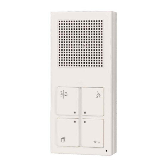
Device overview Loudspeaker Communication Ring tone button button LEDs Light strip Function button Door release button Microphone Indication and operation • Adjustment of ring tone volume Ring tone button • Initiate setting mode for ring tones Indication LED on = Ring tone deactivated •... -
Page 6: Wiring And Installation
Wiring and installation Wiring example 2-wire technique Please observe cable length and loop resistance. No illumination of indoor station in 2 wire installations possible. Slide switch in position II. Indoor station Floor bell button Indoor station Floor bell button Outdoor station Power supply &... -
Page 7: Connecting Diagram
3-wire technique Please observe cable length and loop resistance. Slide switch in position III. Indoor station Floor bell button Indoor station Floor bell button Outdoor station Power supply & control unit Door release relay and illumination Connecting diagram 2-wire operation 3- wire operation Slide switch 2- wire operation... -
Page 8: Installation Of Bottom Shell
Bottom shell Installation of bottom shell • Recommended installation height: 1.5 m • For an easier installation and space for the wires a flush box for wall mounted lamps is recommended (see. figure below). • Place the cable entry over the flush box. •... -
Page 9: Adjust The Device For 2- Or 3-Wire Operation
Top device (reverse side) Adjust the device for 2- or 3-wire operation • 2-wire operation: Factory settings: The slide switch is in position II. The a and b wire will be connected. Combi label • 3- wire operation: Putt he slide switch in position III Slide switch The a, b and P wire will be connected. -
Page 10: Opening The Device
Opening the device 1. On the bottom side of the indoor station is a squared slot to unlock and open the device. Insert a screwdriver (approx. 7mm) with slight pressure straight into the slot. 2. The device can be pulled at the lower side out of the shell (1). -
Page 11: Commissioning
Commissioning • Install all of the devices of the system completely. • Check the a, b and P wires for short-circuit. • Switch on the mains voltage. The following functions are available without additional programming: - existing communication from the indoor stations to the outdoor station - door release function - light switching •... -
Page 12: Function Button
Function button Setting of function button: Internal call, call diversion, door release function and control function Internal call Preparation DCM system is in idle mode. Target indoor station (IS2): Push communication button. Starting setting mode at indoor station (IS1) • Push function button (for approx. 8 s) until you can hear acknowledge tone. - Page 13 Call diversion Preparation DCM system is in idle mode. Target indoor station (IS2): Push communication button. Starting setting mode at indoor station (IS1) • Push function button (for approx. 8 s) until you can hear acknowledge tone. • fast LED flashing •...
- Page 14 Automatic door release Preparation DCM system is in idle mode. • Push function button (for approx. 8 s) until you can hear acknowledge tone. • fast LED flashing • release the function button All LED flashing fast • push door release button •...
-
Page 15: Light Switching
Control function 8 Preparation DCM system is in idle mode. • Push function button (for approx. 8 s) until you can hear acknowledge tone. • fast LED flashing • release the function button All LED flashing fast • push function button •... -
Page 16: Adjusting The Function Button With The Service Device
Adjusting the function button with the service device The initiation starts always with the key combination *95#Ser.-Nr.# . Initiation Call diversion Automatic door release Internal call Control function 8 Parallel function Example: Outdoor station Floor door bell button IS (228515) is assigned to a bell button of the outdoor station. IS (228520) will be parallel assigned to the IS (228515). -
Page 17: Ring Tone Selection
Ring tone selection Sings and symbols acknowledge tone ring tone slow LED flashing: 0.5 s ON / 0.5 s OFF fast LED flashing: 0.125 s ON / 0.125 s OFF LED pulse flashing: 0.5 s ON / 1.5 s OFF LED ON short pushing of button push button until …. -
Page 18: Ring Tone Selection For: Outdoor Station 1, Outdoor Station 2, Internal Call, Floor Bell Button
Ring tone selection for: Outdoor station 1, Outdoor station 2, Internal call, Floor bell button Ring tone for outdoor station 1 (Outdoor station address = 0) Preparation DCM system is in idle mode. • Push ring tone button (for approx. 8 s) until you can hear acknowledge tone •... - Page 19 Ring tone for all other outdoor stations (Outdoor station address > 0) Preparation DCM system is in idle mode. • Push ring tone button (for approx. 8 s) until you can hear acknowledge tone. • fast LED flashing • release the ring tone button. All LED flashing fast •...
- Page 20 Ring tone internal call Preparation DCM system is in idle mode. • Push ring tone button (for approx. 8 s) until you can hear acknowledge tone. • fast LED flashing • release the ring tone button. All LED flashing fast •...
- Page 21 Ring tone floor bell button Preparation DCM system is in idle mode. • Push ring tone button (for approx. 8 s) until you can hear acknowledge tone. • fast LED flashing • release the ring tone button. All LED flashing fast •...
- Page 22 Ring tone selection for sub door call Note: The assignment of a sub door call at the outdoor station is only possible with the service device (see product information of TK-SERVICE). Start setting mode Preparation DCM system is in idle mode. •...
- Page 23 Selection sub door call 2 (Serial-no.+2) All LED are pulse flashing • Push communication button • You can hear the next ring tone. All LEDs are ON for the time of the ring tone, then pulse flashing again The last audible ring tone is selected for the sub door call 2.
-
Page 24: Operation
Operation Start communication, door release, switching light Start communication after incoming call (Door call or internal call) • Incoming call You can hear the selected ring tone and the green LED of the communication button flashes. • Push the communication button to start the connection (max. - Page 25 Stop communication The communication will be stopped: • by means of pushing the communication button (max. 1 s) • when the preset communication time of the outdoor station is elapsed (factory setting: 1min.) • by means of pushing the door release button. Disconnected communication: The LED turns off.
- Page 26 Ring tone volume / Ring tone OFF/ON The ring tone volume is adjustable in 5 levels: 1, 2, 3, 4 and OFF (ring tone is switched OFF). • Push ring tone button (approx. 1 s). • You can hear the adjusted ring tone •...
-
Page 27: Explanation Of Terms And Definitions
Explanation of terms and definitions OS address Every outdoor station is assigned with an outdoor station address. The address enables the differentiation between the various installed outdoor station. Selective communication or door release of e.g. main- or side entrance can be realised. Ready for operation Incoming door call - You can hear a ring tone and the LED at the communication button flashes. - Page 28 Talking mode A communication between indoor and outdoor station will be activated by means of pushing the communication button. Die LED of the communication button is illuminated. The LED of the communication button is flashing, when another indoor station is already communicating with the outdoor station. After elapsed talking time, activating the door release or pushing the communication button again, the device turns back into idle mode.
-
Page 29: General Notes On The Wiring In Dcm Audio Systems
General notes on the wiring in DCM audio systems The cabling depends on the building situation and is only limited by its length. • When selecting the cable length consider: the loop resistance must not exceed max. 20 Ω (table) •... -
Page 30: Technical Data
Principle of loop resistance Measuring loop resistance Rule: Rule: No door communication device shall have a longer Turn OFF 230 V / 50 Hz of the VS. distance from the power supply & control unit than Connect a and b short circuit at the VS. 20 Ohm ! All other devices do not disturb the measuring process and remain connected. -
Page 31: Acceptance Of Guarantee
We accept the guarantee in accordance with the corresponding legal provisions. Please return the unit postage paid to our central service department giving a brief description of the fault: ALBRECHT JUNG GMBH & CO. KG Technique (DCM) Service-Line: 0 23 55 . 80 65 52 Service-Centre Kupferstr.
Need help?
Do you have a question about the TK IS A 514 A Series and is the answer not in the manual?
Questions and answers