Table of Contents
Advertisement
Quick Links
NCD+
Instruction & Maintenance Manual
Do not permit untrained persons to install, operate or maintain the equipment. Do not attempt to install or
operate the equipment until you have read and fully understand these instructions.
If you do not fully understand these instructions, contact your supplier for further information. Be sure to read the Safety
section before utilizing this equipment.
© 2016 Nelson Stud Welding, Inc.
All Rights Reserved.
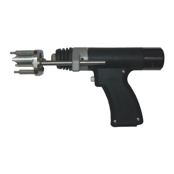
Auto-Gap Gun
(729-110-042)
These instructions are intended for experienced operators.
If you are not fully familiar with the principles of operation and safe practices for arc
welding equipment, we urge you to read AWS SP – "Safe Practices" available from
the American Welding Society.
Page 1
February 2016
Part No. 729-110-042 v1.03
Advertisement
Table of Contents

Related Manuals for Nelson NCD+ Auto-Gap Gun


Summary of Contents for Nelson NCD+ Auto-Gap Gun
- Page 1 If you do not fully understand these instructions, contact your supplier for further information. Be sure to read the Safety section before utilizing this equipment. © 2016 Nelson Stud Welding, Inc. Page 1 All Rights Reserved.
- Page 2 Buyer’s expense after notice to Nelson of the claimed breach, and shall be limited to furnishing a like quantity of such goods free from such defects or, at Nelson’s option, to refunding the purchase price (less reasonable depreciation based on actual use);...
- Page 3 Protection Association, Batterymarch Park, Quincy, MA 02269 Refer to ANSI/ASC Standard Z49.1 (see listing on next page) for specific ventilation recommendations. © 2016 Nelson Stud Welding, Inc. Page 3 All Rights Reserved. February 2016...
- Page 4 Keep hands, hair, loose clothing, and tools away from moving parts. Reinstall panels or guards and close doors when servicing is finished and before reenergizing welder. © 2016 Nelson Stud Welding, Inc. Page 4 All Rights Reserved. February 2016...
-
Page 5: Table Of Contents
Contents Overview ................................7 Nelson NCD+ Welding Modes ........................8 1.1.1 Contact Mode Capacitor Discharge Welding..................8 1.1.2 Gap Mode Capacitor Discharge Welding ...................8 NCD+ Guns ..............................9 1.2.1 Operation of the Auto-Gap Gun (Gap Mode) ..................9 1.2.2 Operation of the Auto-Gap Gun (Contact Mode) ................9 Features ................................ - Page 6 NCD+ CTRL TO GUN, 12 PIN, Auto-Gap ....................25 Specifications ............................26 Accessories .............................. 27 8.4 Table of Weld Parameters ..........................28 Contact Information ............................29 © 2016 Nelson Stud Welding, Inc. Page 6 All Rights Reserved. February 2016 Part No. 729-110-042 v1.03...
-
Page 7: Overview
1 Overview The Nelson NCD+ stud welding guns are made to be used with Nelson NCD+ stud welding power units, which utilize the capacitor discharge principal of stud welding. This system is designed to use fasteners, which are manufactured with a small projection on the weld end and are welded by either the Contact or Gap method. Heat for fusion is obtained from an electric arc, which is established by flashing away the small projection. -
Page 8: Nelson Ncd+ Welding Modes
Each method has its own uses and set-up requirements. The method you select will be determined by the metals to be joined, esthetics, strength and fixturing. Nelson Stud Welding can assist you in determining which method and settings best suit your needs. -
Page 9: Ncd+ Guns
Operation of the Auto-Gap Gun (Gap Mode) The NCD+ Auto-Gap gun is a capacitor discharge lift gun. There are two wires in the control cable that go to the gun coil and two wires that go to the trigger. When the trigger is pulled, the stud rises off the workpiece. The gun de-energizes and the main spring then pushes the stud back towards the workpiece. -
Page 10: Features
TRIGGER CONTROL CABLE WELD CABLE GUN BODY (2 HALVES) FOOT ASSEMBLY BELLOWS SPRING ADJUSTMENT COLLAR MAIN SPRING REAR CAP AND TRAVEL ADJ SCREW © 2016 Nelson Stud Welding, Inc. Page 10 All Rights Reserved. February 2016 Part No. 729-110-042 v1.03... -
Page 11: Gun Set-Up
The chuck must be in firm contact with the stud stop while tightening the chuck nut. Figure 3.1 Chuck and Stop Assembly © 2016 Nelson Stud Welding, Inc. Page 11 All Rights Reserved. February 2016 Part No. 729-110-042 v1.03... -
Page 12: Setting Up Foot And Leg Assembly
Also included with the foot & leg assembly are three locating pins used to make the tripod setup. The spark shield and the locating pins may be used together or independently during welding operations. Figure 3.3b Tripod Foot & Leg Assembly *See section 7 for part numbers © 2016 Nelson Stud Welding, Inc. Page 12 All Rights Reserved. February 2016... -
Page 13: Setting Spring Pressure (Auto-Gap Mode)
Turn the spring pressure adjustment knob to desired spring pressure. For the included standard duty gap spring each mark equates to .25 lbs of spring force and the minimum is 4 lbs. See Fig. 3.3b © 2016 Nelson Stud Welding, Inc. Page 13 All Rights Reserved. -
Page 14: Setting Spring Pressure In Contact Mode
Turn the spring pressure adjustment knob to desired spring pressure. For the contact spring each mark equates to 1 lb of spring force and the minimum is 7 lbs. © 2016 Nelson Stud Welding, Inc. Page 14 All Rights Reserved. -
Page 15: Changing Your Tool To Weld With Contact
6. Remove front cover, part 28, and plastic bearing, part 40. 7. Change part 13 Main spring. 8. Re-assemble in reverse order. 526-001-234 Pre-installed Gap spring 526-001-268 Contact Spring included with tool. © 2016 Nelson Stud Welding, Inc. Page 15 All Rights Reserved. February 2016 Part No. 729-110-042 v1.03... -
Page 16: Weld Setup
During welding, it is very important to draw the chuck (gun) straight off the stud after a weld has been made to avoid spreading the chuck tines. If this procedure is not followed, chuck life may be substantially shortened. © 2016 Nelson Stud Welding, Inc. Page 16 All Rights Reserved. -
Page 17: Maintenance Of Stud Welding System
Always disconnect power before opening any power control unit. CD units may continue to store energy after they have been unplugged. To ensure all energy is discharged, wait at least one minute before removing cover and servicing the power control unit. © 2016 Nelson Stud Welding, Inc. Page 17 All Rights Reserved. -
Page 18: Troubleshooting
NOTE: Do not bend aluminum studs by striking with a hammer, always use a bending tool. The stud weld should not be damaged, only the stud shank or the base material. © 2016 Nelson Stud Welding, Inc. Page 18 All Rights Reserved. - Page 19 This issue can be rectified by: No arc initiation due to timing tip failing to Increasing voltage. flash. Using 10% detergent solution spray mist. © 2016 Nelson Stud Welding, Inc. Page 19 All Rights Reserved. February 2016 Part No. 729-110-042 v1.03...
- Page 20 The object will be to always weld between the cause this problem. grounds. If you need assistance contact your Nelson Representative. Welding near the edge (1/4 inch or less) of Place another piece of sheet metal of the same type and thickness next to the edge you are welding.
-
Page 21: Exploded Drawings & Parts List
WELD CABLE JUMPER 720-519-081 WELD CABLE ASM 721-268-010 CONTROL CABLE ASM 726-013-002 COLLET 729-023-017 WASHER 5mm CONICAL SPRING 751-003-029 DUST BELLOWS 751-458-016 LIFTING RING © 2016 Nelson Stud Welding, Inc. Page 21 All Rights Reserved. February 2016 Part No. 729-110-042 v1.03... - Page 22 REAR CAP ,CD WELD GUN (GAP GUN) 751-650-305 ARMATURE SPRING RETAINER 751-650-306 MOVABLE CORE ASSEMBLY 751-650-309 STOP WASHER 751-650-310 LIFTING RING SPRING WASHER 87-05-22 TRIGGER SPRING,4 WIRE 717-093-003 O-RING,11/16IDx7/8ODx3/32THK © 2016 Nelson Stud Welding, Inc. Page 22 All Rights Reserved. February 2016 Part No. 729-110-042 v1.03...
-
Page 23: Exploded Drawing
7.2 Exploded Drawing © 2016 Nelson Stud Welding, Inc. Page 23 All Rights Reserved. February 2016 Part No. 729-110-042 v1.03... -
Page 24: Electrical Functions Of Guns
Coil Reassemble the rear cap with the slot towards the top of the gun Coil and the front cover with its bottom perpendicular to the gun handle. © 2016 Nelson Stud Welding, Inc. Page 24 All Rights Reserved. February 2016... -
Page 25: Schematics
8 Schematics 8.1 NCD+ CTRL TO GUN, 12 PIN, Auto-Gap © 2016 Nelson Stud Welding, Inc. Page 25 All Rights Reserved. February 2016 Part No. 729-110-042 v1.03... -
Page 26: Specifications
-5°C to 50°C (23°F - 122°F) Operating Temperature (°C) 0°C to 40°C (32°F - 104°F) IP Rating Stud Placement Tolerances +/- 0.010 (0.25 mm) © 2016 Nelson Stud Welding, Inc. Page 26 All Rights Reserved. February 2016 Part No. 729-110-042 v1.03... -
Page 27: Accessories
3/4” - 1-1/8” 500-017-018 508-001-035 HEX KEY SET, METRIC 500-017-019 1-1/4” - 1-5/8” 500-017-020 1-3/4” - 2-1/8” Figure 8.1 Stud Stop Pin Assembly © 2016 Nelson Stud Welding, Inc. Page 27 All Rights Reserved. February 2016 Part No. 729-110-042 v1.03... -
Page 28: Table Of Weld Parameters
Aluminum alloy 3003 was used to set the above parameters. Other alloys may require parameter adjustments. If settings are needed (or desired) other than those listed above, please consult your Nelson representative. © 2016 Nelson Stud Welding, Inc. Page 28 All Rights Reserved. -
Page 29: Contact Information
P.O. Box 4019 Nichelino, (TO) I-10042 Elyria, OH 44036-2019 USA Italy Phone: 440.329.0400 Phone:39.011.6059238 Fax: 440.329.0597 Fax: 39.011.6059230 World Wide Web: NelsonStudWelding.com E-mail: Nelson.Sales@NelsonStud.com © 2016 Nelson Stud Welding, Inc. Page 29 All Rights Reserved. February 2016 Part No. 729-110-042 v1.03...
Need help?
Do you have a question about the NCD+ Auto-Gap Gun and is the answer not in the manual?
Questions and answers