
Subscribe to Our Youtube Channel
Related Manuals for zapco HDSP-V Series


Summary of Contents for zapco HDSP-V Series
- Page 1 HDSP-V AD-A (DCP v.2.9.2) Owner’s Manual Before operating the unit, please read this manual thoroughly and retain it for future reference. Last update November 8, 2019...
- Page 2 (Knowledge from doing) There is absolutely no substitute for experience; that is a simple fact of life. Another simple fact is that ZAPCO has, for over forty years, been the leader in defining quality standards for the car audio industry.
-
Page 3: Table Of Contents
Table of Contents Introduction ........................................4 The revolutionary Zapco HDSP-V Series ........................4 Bar raising numbers for the Zapco HDSP-V ......................5 Upgradable internal modules/components ......................7 HDSP-V PAD-A Input End ................................... 8 HDSP-V PAD-A Output End and Dash Board .......................... -
Page 4: Introduction
The revolutionary Zapco HDSP-V Series From Italy finally comes a masterpiece of engineering that will mark the history of Zapco with a fundamental step from the analog to the digital world, with everything at the highest levels possible today in the high-end audio world. It was made for the car, but the performances are so extraordinary that it's a unique product to use even at home as it can hold up to comparison with home audio products, which have significantly higher prices. -
Page 5: Bar Raising Numbers For The Zapco Hdsp-V
Bar raising numbers for the Zapco HDSP-V The HDSP-V is the best hardware that Zapco has ever built, and the numbers attest to that. Although the HDSP is composed of 18 individual pieces (HDSP-Z16V) put together in a modular version that is easy to adapt or update according to your needs, the background noise and the crosstalk numbers are superb. - Page 6 All-in-one Dual Core Processor - Why a Player with on-board DSP? Players (portable or not), often have a DSP inside, either simple or sofisticated, but it is a DSP. Zapco has been inspired by this to offer its customers a professional DSP with the Player inside. What are the advantagesof our integrated solution compared to that of connecting a Player to the DSP? First, it must be said that not all portable players have a digital output.
-
Page 7: Upgradable Internal Modules/Components
Upgradable internal modules/components Zapco thinks to provide a perfect line of signal path to the speakers and through the listening area. For that reason, hardware and software will be easily up-gradable with different modules that can be changed later as the situation requires. In building the HDSP-V digital processors, we used the very best components we could find for a production product. -
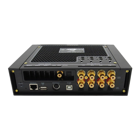
Page 8: Hdsp-V Pad-A Input End
6. PC USB : This USB-B receptacle can be used to connect the HDSP processor to a PC for system setup. : This DIN receptacle will accept the Zapco Wireless Dongle for wireless connection to a 7. WiFi Module PC for system adjustments. -
Page 9: Hdsp-V Pad-A Output End And Dash Board
HDSP-V AD-A Output End and Dash Board The Output end is very straight forward with eight (HDSP-Z16V AD-16A) or four (HDSP-Z16V AD-8A) pairs of Zapco’s proprietary Gold RCA Output connectors. 1A Power Fuse The processor’s Electrical Connections . Below is the wire harness with the wire colors. -
Page 10: Hdsp-V Pad-A Cover Plate
HDSP-V AD-A Cover Plate There is a cover plate in the top of the HDSP processors held in place by screws. Under that plate are the main input controls. Each channel pair has a switch to choose for the main Main (RCA Level) OEM (Speaker Level) analog inputs. -
Page 11: Installing The Control Program (Gui)
Installing the Control Program (GUI) The HDSP-V Zapco processors are controlled by a PC using the Zapco Digital Control Program. The program is available for download on the Zapco website: zapco.com/hdsp-5-support Inside the HDSP-V support page you will find user’s manual, software and firmware download and update options. - Page 12 Windows Drivers The HDSP control program works with Windows system from XP through W-10. In the new 2.9.1 GUI version, we added the signed certification to the driver. This is an autogenerated certification that should be accepted by all the Windows OS from XP to 8.1. This should resolve all the compatibility problems with Windows 7/8/8.1.
-
Page 13: Unit Installation
Unit Installation The first step in the installation of your processor is to disconnect the negative terminal of the battery to prevent damage to the equipment and to the car's electrical system. The HDSP-V processor needs to be securely mounted in a location where it will not be exposed to excessive heat, moisture, or vibration. When choosing a location be sure there is room for all the cables and wiring that will be connected to HDSP-V and be sure you have easy access to the USB control input to connect to the PC. -
Page 14: Input Sensitivity For Radio/Cd Head Unit
To get the best possible signal to noise ratio and the widest dynamic range, you want the HDSP to receive the strongest undistorted signal it can accept. To aid in this, Zapco provides a gain pot and Clip LED for each channel accessed under the top cover as seen earlier in the manual. The first step is to ensure that the Input switch is in the correct position for either MAIN (RCA) or OEM (Speaker level). -
Page 15: Opening The Control Program (Gui)
Opening the Control Program (GUI) When you click on the Zapco HDSP Heatsink icon you get the splash screen below. Notice the GUI version number (here it is v.2.9.1) on the right side under DIGITAL CONTROL PROGRAM. The HDSP Series is an evolving product and any number of features will be added as new technologies become available. - Page 16 If you have already used the GUI and you have previously saved some configurations, you can choose which configuration to upload between Last Saved, Default, Choose from PC, or Choose from DSP Preset.
-
Page 17: The Hdsp-Z16 V Control Program
The HDSP-Z16 V Control Program The HDSP graphic user interface (GUI) currently consists of a Main page and 5 function pages. The function pages allow a user to set all the channels for a particular function at the same time. The Main page then is an at-a-glance review of the settings and allows fine tuning adjustments that may be needed during the equalization stage. - Page 18 : Signal delay allows you to adjust the arrival time of each channel so that it will 3. Delay and Polarity sound as though you are dead center in the car, even though you are likely sitting far to one side or the other.
- Page 19 - The On/Off function of electrical components cause pulses that can be Power ON/OFF Management amplified by the system’s amplifier and cause “POP”noises. The HDSP firmware and software are designed to prevent this. The Power On/Off menu lets you modify the On /Off delays to best suit your system’s needs.
- Page 20 : Most new vehicles have information/warning systems operating through the factory OEM Automix stereo system. Since the HDSP has a considerable number of input choices beyond the factory stereo we have included the OEM Auto-Mix function so your information system will work regardless of your music source.
- Page 21 The GUI for the HDSP processors will lead you through a complete system setup in the shortest possible time by simply putting everything in a logical order of flow. It also follows the Zapco philosophy that the simplest is best. We don’t waste processing power on things that aren’t necessary for tuning. We put it in an advanced phase control that lets you select the exact frequency of a needed phase shift and precisely what the phase shift should be.
-
Page 22: The I/O Page
The I/O Page The first page you need to set up is the I/O (Input/Output) page. Here you define your output channels (Speakers), your input channels and your active input sources. Before starting you need to know what inputs you are using, what speakers you are using, and how many output channels you will have. -
Page 23: Defining Inputs
c) Once that is done, you click SET and the system will adjust the speaker diagram, install default crossovers, and open (or clear) the I/O matrix so you can assign the needed inputs to each output channel. Defining Inputs To the right of the OUTPUT section is the I/O Matrix. When you choose your input and click SET, the input squares in the matrix open and they say ON at the top. - Page 24 After you have defined your system with the Main input you will want to set up the HD Player, any digital inputs you are using and the LINE input, if that is available, by choosing the desired source and then choosing SET. Below is the same system you see above, with all the inputs configured.
-
Page 25: Auto-Summing
Auto-Summing OEM SUM: If you are using OEM inputs and need to sum channels you can do that manually by clicking in each of the appropriate boxes in the matrix. However, the GUI will also do that for you automatically with the touch of a button. -
Page 26: The Delay Page
The Delay Page The ideal position for listening to a stereo system is dead center between the two speakers forming a equilateral triangle. That way the sounds from each speaker will arrive to you at the proper time to give you a good and accurate impression of the width and depth of the sound stage and each instrument’s place in it. - Page 27 The delay page lets you adjust delay by . Distance can be measured in either CM or Time Distance INCH units. Simply clicking the measurement unit at the top of the column changes it to the other unit. To set the delay and make it appear that all speakers are the same distance from you: a.
-
Page 28: The Crossover Page
The Crossover Page Above, you see the crossover page of a 12-channel system with channels 1/2 highlighted. When you fill in the I/O page, default crossovers are set for each speaker. On the crossover page you can modify the default values to match the needs of your particular speakers. There are HIGH PASS and LOW-PASS filters available for every output channel. - Page 29 Using the Crossover Page First note the Blue link buttons for each pair of speakers. All speakers used in pairs should be linked to assure that left and right crossovers are identical. As you set crossover values, the crossovers trace will show in two places.
-
Page 30: The Phase Page
The Phase Page Note: This section concerns the Phase. We included an advanced phase control in the HDSP-V GUI. Phase control can be a magic bullet to solve some tuning issues. However, it can also do far more harm than good to the sound stage, if used incorrectly or used to much. - Page 31 When you open the phase page you will see that the frequency choice has already been made by default at the high pass crossover frequency of all channels except the subwoofer channels, which needs only low pass filters. This is because almost all times a phase shift is used it is to correct a frequency null (no sound) caused by the inherent phase shift made by the crossover filters.
-
Page 32: The Vseq Page
The VSEQ Page Over the past few years more and more auto makers have been using digital processors to modify frequency response as volume changes. The VSEQ is used to overcome this with an active EQ band in each channel that can be turned on and off by the volume of the OEM radio. The most common issue is that the car maker reduces the amount of bass as volume increases. -
Page 33: The Equalizer
The Equalizer The Zapco HDSP-Z16 V has a unique advanced equalizer. Processors have a hurdle; Low frequencies take a great deal of processing power. The common practice then is to “downsample” the bass frequencies on the assumption that you won’t hear it. Since our chip has twice the processing power of other processors, we doubled the processing power of the first 15 bands so you have the same accuracy in the bass areas as you have in the easier upper mid and high ranges. - Page 34 Another tool is the Mute/Solo column. These buttons allow you to mute the speakers you do not want to hear or to listen to only one speaker at a time. As mentioned early in the manual, right clicking any mute button lets you Mute All or Un-Mute All. Also remember the Reset functions under the FILE menu if you want to undo a setting.
- Page 35 When you click on one of the EQ band buttons you will see what band you are using (1 to 30), the frequency you are at, and the Gain (+ or -) that you are applying. The Q and Gain blocks for that button will be Highlighted below.
-
Page 36: Speaker Polarity And Phasing
Speaker Polarity and Phasing You were promised more on polarity. Before equalization you should assure that all speakers are in phase as a system at the listening position. All speakers need to have the same polarity so they move the same direction at the same time. If they are not, you will not be able to get a proper tune. There are a number of methods for doing this. -
Page 37: Tuning - The Simple Rules
Tuning - The Simple Rules Before you can get what you want, you need to know what you want. In the graphs below, we look at some different response curves and what they mean and sound like. Keep in mind that these illustrations are NOT what your EQ graph looks like. They are what your RTA looks like. If you have a flat response like below on your RTA, your EQ graph will have lots high spots and low spots to make the RTA graph look like that. - Page 38 : Here is a problem curve. The small variations in blue are OK. They are 2dB or less and Problem Curve you likely will never hear them. However, the variations in the red circles are bad. While the ear is not so sensitive to dips in the response, it is very sensitive to peaks.
-
Page 39: Dash Board Control
Dash Board Control The Player is controlled by an 3”Touch Screen color display. It is housed in an elegant aluminum CNC case and it can also be used to control volume, fader, balance, tone, some set-up of the system, and to switch instantaneously, by touch screen, from different tuning presets (up to 10 memory presets). - Page 40 SYSTEM shows some information about the system status and other functions. The page allows you to choose DISPLAY to adjust the brightness of the Dashboard display. VER will show you the Software and Firmware versions of the processing components currently installed. DSP brings up clipping indicators for each of the 8 input channels.
- Page 41 The AUDIO page gives you adjustments for balance and fader, and for Bass, Midrange and Highs. The arrow in the lower corner returns to the previous page. When you choose HD PLAYER you will get the directory. The directory shows files loaded singly and also folders.
-
Page 42: Formatting Larger Usb Thumb Drives/Sticks
Formatting Larger USB Thumb Drives/Sticks Of course, before you play HD Music you have to have the HD files. There are many download sites where you can get the files (HDTracks.com is just one). You need to download the files onto a USB drive. -
Page 43: Hd Player Quick Start
Special Features of the HDSP-Z16V Processor The unique I/O page of the HDSP-Z16V processor allows some useful special effects to happen. A little about how it all works: a. You can assign any combination of inputs to any processing channel by adding or subtracting inputs (you subtract but adding an input with its phase reversed). - Page 44 1. You can remove the Right Ch information from the Left channel and remove the Left Ch information from the Right channel by reversing the phase of the added channel. So Right is added out of phase to the Left and Left is added out of phase to the Right, without the center channel information. The rear information is no longer the same as the front information.
-
Page 45: Creating A Pair Of 60-Band Equalizer Channels
Creating a Pair of 60-Band Equalizer Channels The Loop function of the HDSP-Z16 V can also be used to create a pair of 60-band EQ channels, This will allow ultimate fine tuning of systems (especially in competition) that use wide-range speakers for the midrange and high frequencies. - Page 46 So, to save processing power, the common practice is to simply down-sample the lower frequencies on the assumption that you will never know. Zapco has taken a different approach, we absolutely loaded up power on bands 1~15 with double precision filters because if you want it to sound right you can’t just do the easy stuff.
-
Page 47: Firmware Update
Firmware Update Standard procedure with new digital equipment is to check for updates. The current software and firmware for the HDSP processors will always be on the HDSP support page. When you open your GUI you will see the current installed software version. When you turn on the HDSP and go to System on the Dash Controller you will find the firmware version currently installed in the HDSP. - Page 48 • Click on the .exe file to open the System Upgrade Tool below • Double check items 1 through 4 below to assure it is ready for the update • Choose Select upgrade package and navigate back to your Downloads to find HDSP-Firm_v1.0.7 (or the current version) •...
-
Page 49: Technical Specifications
Technical Specifications OMAP L-138 - 2 x 456 MHz - 32 Bit (till 64-bit / IEEE double precision) DSP Processor Processor Point: Fixed & Floating Sampling Rate: 96 KHz (HDSP-Z16V), 192 KHz (HDSP-Z8V) Player Power 456 Mhz - Arm 9 32 Bit WAV, AIF, AIFF, FLAC, ALAC, AAC, MP3 Audio Formats Standard: AK5558, 32 Bit, 784 KHz, DR 115 dB... - Page 50 Apex, Aprilia ITALY Since 1974 zapco.com...
Need help?
Do you have a question about the HDSP-V Series and is the answer not in the manual?
Questions and answers