Table of Contents
Advertisement
Advertisement
Table of Contents

Subscribe to Our Youtube Channel
Related Manuals for Current Solutions LG SMART TENS


Summary of Contents for Current Solutions LG SMART TENS
- Page 1 LG SMART TENS INSTRUCTION MANUAL r � : . . . • - .
- Page 2 This manual is valid for the LG SMART TENS Stimulator This user manual is published by Current Solutions™, LLC Current Solutions™, LLC does not guarantee its contents and reserves the right to improve and amend it at any time without prior notice.
-
Page 3: Table Of Contents
TABLE OF CONTENTS 1. SAFETY INFORMATION…..…………………………....…….4 1.1 General 1.2 Medical background 1.3 Indication for use 1.4 Contraindications 1.5 Warnings, Cautions, Adverse Reactions 2. PRESENTATION……………………………..……....… 10 2.1 Front and Rear panel 2.2 LCD display 3. SPECIFICATION………………………………………....….. 13 3.1 Accessories 3.2 Technical information 3.3 The waveforms of the stimulation programs 4. -
Page 4: Safety Information
1. SAFETY INFORMATION 1.1 General LG SMART TENS stimulator is a portable electrotherapy device featuring Transcutaneous Electrical Nerve Stimulation (TENS) therapeutic device, which is used for pain relief. The stimulator sends a gentle electrical current to underlying nerves and muscle group via electrodes applied on the skin. The parameters of device are controlled by the buttons. -
Page 5: Indication For Use
You may discuss this with your physician or therapist. 1.3 Indication for use LG SMART TENS Stimulator should be used for the Symptomatic relief of chronic intractable pain, acute post traumatic pain, acute post surgical pain and arthritis pain. -
Page 6: Warnings, Cautions, Adverse Reactions
present in the treatment area. Stimulation should not be applied over swollen, infected, inflamed areas or skin eruptions (e.g. phlebitis, thrombophlebitis, varicose veins, etc.). Electrodes must not be applied to sites that might cause current/stimulation to flow through the carotid sinus region (anterior neck) or transcerebrally (through the head). - Page 7 carotid sinus reflex. Stimulation should not be applied over the anterior neck or mouth. Severe spasm of the laryngeal and pharyngeal muscles may occur and the contractions may be strong enough to close the airway or cause difficulty in breathing. Stimulation should not be applied transthoracically in that the introduction of electrical current into the heart may cause cardiac arrhythmias.
- Page 8 CAUTIONS: Federal law (USA) restricts this device to sale by or on the order of a physician. For single patient use only. Keep yourself informed of the contraindications. This stimulator not intended for unattended, personal use by patients who have noncompliant, emotionally disturbed, dementia, or low IQ.
- Page 9 hypersensitivity due to the electrical stimulation or silicone rubber. If rash develops or pain persists, discontinue use and consult a doctor. 14) Electrode placement and stimulation settings should be based on the guidance of prescribing practitioner. 15) Effectiveness is highly dependent upon patient selection by a person qualified in the management of pain afflicted patients.
- Page 10 presence of explosive atmosphere and flammable mixture. ADVERSE REACTIONS: Skin irritation from the electrode gel and electrode burns are potential adverse reactions. If skin irritation occurs, discontinue use and consult your physician. If the stimulation levels are uncomfortable, reduce the stimulation Intensity to a comfortable level and contact your physician if problems persist.
-
Page 11: Presentation
2. PRESENTATION 2.1 Front and Rear Panel LG SMART TENS Output socket. 2) Adapter Receptacle. 3) LCD display: Shows the operating state of the device. 4) Increasing the output intensity of channel 1. 5) Decreasing the output intensity of channel 1. -
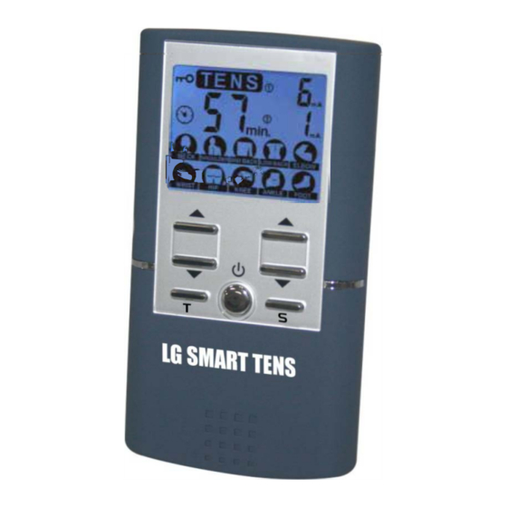
Page 12: Lcd Display
2.2 LCD Display Display TENS therapeutic mode. Lock function indicator. Low-battery indicator. Display numbers of the treatment time. Timer symbol. Display numbers of the output intensity for channel 1. Display numbers of the output intensity for channel 2. Display therapeutic program by body part. -
Page 13: Specification
3. SPECIFICATION 3.1 Accessories No DESCRIPTION Q’TY TENS stimulator device 1 piece Electrodes Leads 2 pieces 40mm x 40mm adhesive electrodes 4 pieces 9V Alkaline Battery, type 6LR61 1 piece Instruction Manual 1 piece Carrying case 1 piece 3.2 Technical Information Channel Dual, isolated between channels 9.0 V Alkaline battery, type: 6LR61... -
Page 14: The Waveforms Of The Stimulation Programs
Technical specifications Waveform Mono-phase square pulse wave Pulse Adjustable, 0~105mA peak at 1000 ohm amplitude Load each channel, 1mA/Step. Pulse Width From 100 to 260us microseconds Pulse Rate From 50 to 150 Hz 3.3 The waveforms of the stimulation programs Normal Pulse Width Modulation Cycle time... -
Page 15: Instruction For Use
4. INSTRUCTION FOR USE 4 .1 Battery 4.1.1 Check/Replace the battery Over time, in order to ensure the functional safety of device, changing the battery is necessary. Slide the battery compartment cover and open. Insert the 9V battery into the battery compartment. -
Page 16: Battery
If a battery has leaked, avoid contact with skin, eyes and mucus membranes, Rinse the affected spots with lots of clear water immediately and contact a physician right away. Battery may not be charged, dismantled, thrown into fire or short-circuited. Protect battery from excess heat;... -
Page 17: Connect Lead Wires To Device
4.3 Connect lead wires to device Before proceeding to this step, be sure the device is completely turns OFF. The wires provided with the system insert into the jack sockets located on top of the device. Holding the insulated portion of the connector, push the plug end of the wire into one of the jacks (see drawing);... - Page 18 4.4.2 Place electrodes on skin Apply electrodes to the exact site indicated by your physician or therapist, before applying electrodes, be sure the skin surface over which electrodes are placed is thoroughly cleaned and dried. Make sure the electrodes are placed firmly to the skin and make good contact between the skin and the electrodes.
-
Page 19: Turn On
4.6 Select the therapeutic part program LG SMART TENS Stimulator with 10 pre-set programs, the details please refer to Page 21 <Programs>. The therapeutic part program can be selected by pressing the [ S ] button control. -
Page 20: Safety Lock Feature
2) If the electrodes no placed firmly on skin or the device has not connected on the electrodes, the stimulator's output intensity surpasses 12mA, the intensity will enulls automatically. 3) You can press [S] button to stop the treatment if you want, and the device enter into waiting mode(If the button is locked, you should press only one of the [▼] button first) -
Page 21: Program
5. PROGRAMS Treatment Therapeutic Frequency Pulse Wide Waveform time (Min) part program (Hz) (us) default NECK Modulation 60-100 100-150 Pulse rate 800-100 SHOULDER modulation Pulse rate MID BACK 100-150 modulation Frequency LOW BACK 50-80 modulation ELBOW Continuous WRIST Continuous Pulse rate 100-150 modulation Pulse width... -
Page 22: Cleaning And Care
6. CLEANING AND CARE 6.1 Tips for skin care To avoid skin irritation, especially if you have sensitive skin, follow these suggestions: Wash the area of skin where you will be placing the electrodes, using mild soap and water before applying electrodes, and after taking them off. -
Page 23: Electrodes
6.3 Electrodes Use the device only with the leads and electrodes provided by the manufacturer. Use only the electrode placements and stimulation settings prescribed by your physician or therapist. It is recommended that, at minimum, 40mm*40mm self-adhering based, square electrodes are used at the treatment area. -
Page 24: Cleaning The Electrodes Cords
Apply the protective backing to the tacky side of the electrode. Place the electrode on the side of the protective backing that is labeled with the word on. It may be helpful to improve repeated application by spreading a few drops of cold water over the adhesive and turn the surface up to air dry. - Page 25 responsible for the results of maintenance or repairs by unauthorized persons. The user must not attempt any repairs to the device or any of its accessories. Please contact the retailer for repair. Opening of the equipment by unauthorized agencies is not allowed and will terminate any claim to warranty.
-
Page 26: Troubleshooting
7. TROUBLESHOOTING If your device does not seem to be operating correctly, refer to the chart below to determine what may be wrong. Should none of these measures correct the problem, the device should be serviced. Problem Possible Cause Solution 1. - Page 27 3. If still intermittent after replacing lead wire, a component may have failed. Call the repair department. Some programs will seem intermittent. This is expected. Refer to the Program Program option in Option Controls in the Operation section for a description of the program option.
-
Page 28: Storage
8. STORAGE For a prolonged pause in treatment, store the device in a dry room and protect it against heat, sunshine and moisture. Store the device in a cool, well-ventilated place Never place any heavy objects on the device. 9. DISPOSAL Used fully discharged batteries must be disposed of in a specially labeled collection container, at toxic waste collection points or through an... - Page 29 emissions Class B CISPR11 The device is suitable for use in all establishments other than domestic and those directly Harmonic connected to the public low- emissions voltage power supply network that supplies buildings used for applicable 61000-3-2 domestic purposes. Voltage fluctuations /flicker applicable...
- Page 30 ±2kV for Not applicable Mains power quality Electrical power supply should be that of a fast lines typical commercial transient/ ±1kV for or hospital burst IEC input/output environment. 61000-4-4 lines ±1kV Surge Not applicable Mains power quality differential should be that of a 61000-4-5 mode typical commercial...
- Page 31 Guidance and- manufacturer's declaration. Electromagnetic immunity The device is intended for use in. the electromagnetic environment specified below. The customer or the user should assure that it is used in such an environment. Immunity IEC 60501 Compliance Electromagnetic test test level level environment - guidance...
- Page 32 Where P is the maximum output power rating of the transmitter In watts (W) according to the. Transmitter manufacturer and d is the recommended separation distance in meters (m). Field strengths from fixed RF transmitters, as determined by an electromagnetic site survey,a should be less than the compliance level in...
- Page 33 Recommended separation distances between portable and mobile RF communications equipment and the device The device is intended for use in an electromagnetic environment in which radiated RF disturbances are controlled. The customer or the user of the device can help prevent electromagnetic interference by maintaining a minimum distance between portable and mobile RF communications equipment (transmitters) and the as recommended below, according to the...
-
Page 34: Glossary Of Symbols
For transmitters rated at a maximum output power not listed above, the recommended separation distance d in meters (m) can be estimated using the equation applicable to the frequency of the transmitter, where P is the maximum output power rating of the transmitter in watts (W) accordable to the transmitter manufacturer. -
Page 35: Warranty
12. WARRANTY Please contact your dealer in case of a claim under the warranty. If you have to send in the unit, enclose a copy of your receipt and state what the defect is. The following warranty terms apply: 1) The warranty period for device is one year from date of purchase.
Need help?
Do you have a question about the LG SMART TENS and is the answer not in the manual?
Questions and answers