Table of Contents
Advertisement
Advertisement
Table of Contents

Related Manuals for Current Solutions InTENSity Select Combo


Summary of Contents for Current Solutions InTENSity Select Combo
- Page 1 SELECT Combo INSTRUCTION MANUAL...
- Page 2 This manual is valid for the InTENSity Select Combo TENS/IF/MIC/EMS Stimulator This user manual is published by Current Solutions™, LLC Current Solutions™, LLC does not guarantee its contents and reserves the right to improve and amend it at any time without prior notice.
-
Page 3: Table Of Contents
Table of Contents 1. SAFETY INFORMATION…..…………………………....1.1 General description 1.2 Medical background 1.3 Indication for use 1.4 Contraindications 1.5 Warnings, Cautions, Adverse Reactions PRESENTATION………………………………………………….. . 2.1 Front and Rear panel 2.2 LCD display 3.SPECIFICATION………………………………………………...… 3.1 Accessories 3.2 Technical information 3.3 The waveforms of the stimulation programs 4.INSTRUCTIONS FOR USE ………………………………...……... -
Page 4: Safety Information
1. Safety information 1.1 General InTENSity Select Combo is a portable electrotherapy device featuring four therapeutic modes : Transcutaneous Electrical Nerve Stimulation (T pain relief and electrical muscle stimulation. The stimulator sends gentle electrical current to underlying nerves and muscle groups via electrodes applied on the skin. - Page 5 only helps control the pain. TENS does not work for everyone; however, in most patients it is effective in reducing or eliminating the pain, allowing for a return to normal activity. HOW TENS WORKS There is nothing “magic” about Transcutaneous Electrical Nerve Stimulation (TENS).
- Page 6 HOW EMS WORKS The EMS units send comfortable impulses through the skin that stimulate the nerves in the treatment area. When the muscle receives this signal it contracts as if the brain has sent the signal itself. As the signal strength increases, the muscle flexes as in physical exercise.
-
Page 7: Indication For Use
WHAT IS MICROCURRENT? Microcurrent stimulation is a type of therapy in which very low current is sent into the cells of the body. Microcurrent is a very faint current that is so small it is measured in millionths of an amp (Microamps). -
Page 8: Contraindications
IMPORTANT SAFETY INFORMATION! Read the instruction manual before operation. Be sure to comply with all “Contraindications”, “Warnings”, “Cautions” and “Adverse reactions” in the manual. Failure to follow instructions can cause harm to user or device. 1.4 Contraindications... -
Page 9: Warnings, Cautions, Adverse Reactions
1.5 Warnings, Cautions and Adverse Reactions WARNINGS:... - Page 11 CAUTIONS: Federal law (USA) restricts this device to sale by or on the order of a physician. For single patient use only. Keep yourself informed of the contraindications. This stimulator not intended for unattended, personal use by patients who have noncompliant, emotionally disturbed, dementia, or low IQ.
- Page 12 14) Electrode placement and stimulation settings should be based on the guidance of prescribing practitioner. 15) Effectiveness is highly dependent upon patient selection by a person qualified in the management of pain afflicted patients. 16) Isolated cases of skin irritation may occur at the site of the electrode placement following long-term application.
- Page 13 Adverse Reactions: 1) Skin irritation from the electrode gel and electrode burns are potential adverse reactions. If skin irritation occurs, discontinue use and consult your physician. Note: Always use electrodes that are legally marketed and sold in the United States under 510K guidelines. 2) If the stimulation levels are uncomfortable, reduce the stimulation Intensity to a comfortable level and contact your physician if any problems persist.
-
Page 14: Front And Rear Panel
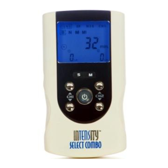
2. Presentation 2.1 Front and Rear Panel 1) Output socket: electric signal output after connection of the cable with adhesive electrodes on channel 1. 2) Output socket: electric signal output after connection of the cable with adhesive electrodes on channel 2. 3) Increasing the output intensity of channel 1 [▲]. -
Page 15: Lcd Display
Decreasing the output intensity of channel 2 [▼]. Use to set the application program and the parameter of the waveform in the setting state. Use to unlock the current treatment program. Parameter Selection: press the button to enter setting state; you can select the different parameters in conjunction with [▲] and [ ▼]. -
Page 17: Accessories
3. Specification 3.1 Accessories 3.2 Technical information Channel Dual, isolated between channels Power supply 9.0 V Alkaline DC -1 *6LR61 battery Adapter output: 9.0Vdc, 800mA(optional) 5°C to 40°C (41℉ to 104℉)with a relative Operating conditions humidity of -10°C to 50°C (14℉ to 122℉)with a relative Storage conditions humidity of Dimensions... - Page 18 Technical specifications for Transcutaneous Electrical Nerve Stimulator (TENS) mode Waveform Mono-phase square pulse wave Pulse amplitude Adjustable, 0~105mA peak at 1000 ohm Load each channel, 1mA/Step. Pulse Width Adjustable, om 50 to 300us microseconds 10μS/step Pulse Rate Adjustable, from 1 to 150 Hz , 1 Hz/step Burst (B) Burst rate: Adjustable, 0.5 ~ 5Hz Pulse width adjustable, 50~300μS...
- Page 19 Technical specifications for Electrical Muscle Stimulation (EMS) mode Waveform: Mono-phase square pulse wave Pulse amplitude Adjustable, 0~105mA peak at 1000 ohm Load each channel, 1mA/Step. Pulse Width Adjustable, from 50 to 300μS microseconds, 10μS/step. Pulse Rate Adjustable, from 1 to 150 Hz, 1 Hz/step Contraction time Adjustable, 1~60 seconds , 1 Sec./ step Relaxation (OFF)
- Page 20 Technical specifications for Interferential (IF) mode Waveform Bi-phase square pulse Pulse amplitude Adjustable, 0~70mA peak to peak at 1000 ohm Load Pulse Rate Channel 1 – Fundamental frequency: 4000 Hz fixed Channel 2 – Selectable frequency: 4001 to 4150 Hz Interference frequency: 1 to 150 Hz.
-
Page 21: The Waveforms Of The Stimulation Programs
3.3 The waveforms of the stimulation programs Burst (B) Normal (N) Pulse Width Modulation Pulse Rate Modulation... - Page 22 Synchronous(S) Alternate (A) Delay (D) Interferential Microcurrent (Constant)
-
Page 23: Instructions For Use
4. Instructions for use 4 .1 Battery 4.1.1 Check/Replace the battery Over time, in order to ensure the functional safety of device, the battery must be periodically changed. 1) Slide the battery compartment cover and open. 2) Insert the 9V battery into the battery compartment. -
Page 24: Connect Electrodes To Lead Wires
4.2 Connect electrodes to lead wires Insert the lead wire connector into electrode connector (standard 0.08 inch female connection). Make sure there are no bare metal of the pins exposed. Caution: Always use the electrodes with the requirements of the IEC/EN60601-1, ISO10993-1/-5/-10 and IEC/ EN60601-1-2, such as with CE mark, or which are legally marketed in the US under 510(K) listing. -
Page 25: Electrodes
4.4 Electrode 4.4.1 Electrode options The electrodes are disposable and should be routinely replaced when they start to lose their adhesive nature. If you are unsure of your electrodes adhesive properties, order replacement electrodes. Replacement electrodes should be re-ordered through or on the advice of your physician to ensure proper quality. -
Page 26: Turn On
4.4.3 Electrode placement The placement of electrodes can be one of the most important parameters in achieving success with therapy. Of utmost importance is the willingness of the physician to try the various styles of electrode placement to find which method best fits the needs of the individual patient. -
Page 27: Steps To Set A New Program
4.7 Steps to Set a New Program 4.7.1 TENS Setting Press the [S] button cycle to enter the setting state. The settings can be adjusted according to the following steps: 1) Set the Therapeutic Program There are 4 programs in TENS therapeutic mode available –Burst (B), Normal (N), Pulse Width Modulation (M), and Pulse Rate Modulation (M1). - Page 28 4.7.2 EMS Setting Press the [S] button cycle to enter the setting state. The settings can be adjusted according to the following steps: 1) Set the Therapeutic Program There are 3 programs in EMS therapeutic mode available – Synchronous, Alternate and Delay.
- Page 29 0 to the setting level, and from the setting value to 0. When the ramp time is set, each contraction may be ramped up and down in order that the signals come on and come off gradually and smoothly. The ramp time is adjustable from 1 to 6 seconds. 7) Set Contract Time The contract Time controls the time of stimulation and can be adjusted.
- Page 30 Press [▲] or [▼] control to adjust setting. You can set the timer to “Continuous” mode by pressing the [▲] button when it shows 60 minutes. Its output will be shut off when time is up. 3) Set Interference frequency (optional) Channel 1 has 4000 Hz fixed Fundamental frequency.
-
Page 31: Adjust Channel Intensity
4) Set Pulse Rate Pulse rate is adjustable from 1 Hz to 150 Hz. Press [S] button cycle to enter this menu, and then press [▲] or [▼]button to adjust the setting. 5) Set Cycle Time (Optional) Cycle time is adjustable form 5 to 30 seconds. Only modulation mode has this parameter setting. -
Page 32: Stop The Treatment
4.10. Stop the treatment When you have activated the treatment timer,you can press the [M] button or the [▼] button to control stop the treatment. Caution: Default state, if the button is locked, you can press only one of the [▼] buttons to unlock, and then press the [M] button or the [▼] button to control stop the treatment. -
Page 33: Program
5. Program Mode Program Modulation Frequency Pulse Treatment time Method Width 50-300us 1-60min,continuous TENS 1-150Hz 50-300us 1-60min,continuous d l ti 1-150Hz 50-300us 1-60min,continuous modulation 1-150Hz 50-300us 1-60min,continuous mode 1-150Hz 50-300us 1-60min,continuous Mode 4kHz 125us 1-60min,continuous modulation 4001-4010Hz 4kHz 125us 1-60min,continuous modulation 4001-4150Hz 4kHz... -
Page 34: Cleaning The Device
3) Wipe the area with the skin preparation your clinician has recommended. Let this dry. Apply electrodes as directed. 4) Many skin problems arise from the “pulling stress” from adhesive patches that are excessively stretched across the skin during application. To prevent this, apply electrodes from center outward;... - Page 35 To use these electrodes: 1) Attach the electrode to the lead wire. 2) Remove the protective backing from the electrode surface. Do not throw away the protective backing because it is reused after the treatment session has been completed. 3) Place the tacky surface to the prescribed skin area by pressing the electrode firmly against the skin.
-
Page 36: Maintenance
) 7 Always use the electrodes with the requirements of the IEC/EN60601-1, ISO10993-1/-5/-10 and IEC/ EN60601-1-2, such as with CE mark, or are legally marketed in the US under 510(K) procedure. 6.4 Cleaning the Electrode's cords Clean the electrode cords by wiping them with a damp cloth. Coating them lightly with talcum powder will reduce tangles and prolong the life. -
Page 37: Troubleshooting
7. Troubleshooting If your device does not seem to be operating correctly, refer to the chart below to determine what may be wrong. Should none of these measures correct the problem, the device should be serviced. Proble Possible Cause Solution Display fails to Battery contact failure 1. -
Page 38: Storage
8. Storage 1) For a prolonged pause in treatment, store the device in a dry room and protect it against heat, sunshine and moisture and remove the battery. 2) Store the device in a cool, well-ventilated place 3) Never place any heavy objects on the device. 9. -
Page 39: Electromagnetic Compatibility(Emc)Tables
10. Electromagnetic Compatibility (EMC) Tables Guidance and manufacturer’s declaration - electromagnetic emissions The device is intended for use in the electromagnetic environment specified below. The Emissions test Compliance Electromagnetic environment - guidance RF emissions Group 1 The device uses RF energy only for its internal function. - Page 40 Guida nce and m manufactu urer’s decl laration. E Electromag gnetic imm munity The de evice is inte ended for use in the electroma gnetic env vironment s specified b below. The cu ustomer or Immun nity IEC 6 60501 mpliance Electroma agnetic en...
-
Page 41: Glossary Of Symbols
Recomm mended se eparation d distances b between portable and mobil le RF com munication ns equipme ent and the e device The d device is in tended for r use in an electroma agnetic env vironment i in which ra adiated RF dis sturbances... -
Page 42: Warranty
12. Warranty Please contact your dealer in case of a claim under the warranty. If you have to send the unit back to your provider, enclose a copy of your receipt and state what the defect is. The following warranty terms apply: 1) The warranty period for device is one year from date of purchase. - Page 44 Manufactured for: Current Solutions 3814 Woodbury Drive Austin,TX 78704 Ph:(800)871-7858 www.currentsolutionsnow.com...
Need help?
Do you have a question about the InTENSity Select Combo and is the answer not in the manual?
Questions and answers