Table of Contents
Advertisement
Quick Links
Rechargeable Smart Lithium Ion Battery
SE-2015
User's Manual
SEALED ENERGY SYSTEMS ®
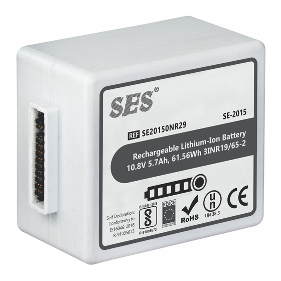
Reference Part Numbers for Battery Model SE-2015
SE20150NR29
10.8V 5.7AH, 61.56Wh
Statement of Confidentiality
The information contained within this document is confidential and
proprietary to Sealed Energy Systems. This information should not, in
whole or in part, be reproduced, disclosed or used except as
expressly and duly authorized by Sealed Energy Systems.
User Manual
1
Advertisement
Table of Contents

Related Manuals for SES SE-2015


Summary of Contents for SES SE-2015
- Page 1 User Manual Rechargeable Smart Lithium Ion Battery Reference Part Numbers for Battery Model SE-2015 SE-2015 SE20150NR29 10.8V 5.7AH, 61.56Wh User’s Manual Statement of Confidentiality The information contained within this document is confidential and proprietary to Sealed Energy Systems. This information should not, in whole or in part, be reproduced, disclosed or used except as expressly and duly authorized by Sealed Energy Systems.
-
Page 2: Table Of Contents
User Manual TABLE OF CONTENTS 3.3.2. SMBus Logic Levels 3.3.3. SMBus Data Protocols 3.3.4. SMBus Host-to-Battery Message Protocol REVISION HISTORY 3.3.5. SMBus Battery-to-Charger Message Protocol 3.3.6. SMBus Battery Critical Message Protocol INTRODUCTION 3.3.7. Host to Battery Messages (Slave Mode) 2.1. SCOPE 3.3.8. -
Page 3: Revision History
Lithium Ion battery SE-2015 by Sealed Energy Systems (SES®). This specification is the interface Certificate of document between SES® and its customers. It is understood that the compliance, EU REACH customer may create their own internal specification. However, this Regulation no. -
Page 4: General Precautions
User Manual In the event of a battery leaking, do not allow the liquid to come in contact with the skin or eyes. If contact has been made, wash the affected area with copious amounts of water and seek medical advice. Keep batteries clean and dry. Secondary batteries need to be charged before use. -
Page 5: Disposal
User Manual 2.3.4 Disposal information regarding disposal of spent batteries. If the internal cells are leaking/broken open, consult hazardous waste regulations under US Environmental Protection Regulations vary for different countries. Dispose of in Agency’s Resource Conservation and Recovery Act accordance with local regulations. -
Page 6: Requirements
User Manual Taiwan: Expended battery packs are not considered hazardous exposed to a damaged leaking cell should be considered hazardous waste. Cells and batteries should be recycled at an waste and disposed of in accordance to local rules and regulations. appropriate collection site... - Page 7 User Manual 3.1.4. Discharge -20C to +60C Discharge Temperature Limits: As shown below, ≤ 80%RH The battery shall be capable of continuous discharge within the Operating Boundary as shown in the graph below. Host devices should be designed for a controlled shutdown following battery notification of termination by the battery sending TERMINATE_DISCHARGE alarm, prior to protection circuit cut-off.
- Page 8 User Manual 3.1.5. Charge 0 C to 45 C Charge Temperature Limits: As Shown below, ≤80%RH The battery shall be capable of continuous charge at 12.6V, as shown in the graph below. A dedicated level II or level III smart battery charger is required to charge the battery.
-
Page 9: Discharge
User Manual 3.1.6. Storage adjacent to the positive terminal. The SMBus Clock and data lines require separate pull-ups to system logic voltage, NOT the Storage Temperature Limits: -20°C to 60°C, ≤80%RH battery voltage. Typically, a 10KΩ pull-up resistor is used, but The battery should be stored in an environment with low ... - Page 10 User Manual performance of the battery. It’s primary functions are to provide down the micro- controller and all associated circuitry. If this fuel gauging and software based charge control, and to ensure should happen, the battery will require an initial low current safe operation throughout the life cycle of the battery.
-
Page 11: Dc Specifications
User Manual 3.2.2. DC Specifications 3.2.3.2. Temperature The internal pack temperature is measured by an NTC PARAMETER LIMITS REMARKS thermistor attached to the cell stack. Temperature readings have a resolution of 0.1°K. The absolute When a host is detected Active mode current accuracy is ±3°K over an operating range of -20°C to <650µA... -
Page 12: Smbus And Sbd Parameters
User Manual 3.3.2. SMBus Logic Levels RSOC LED1 LED2 LED3 LED4 LED5 NOTE At below 10% Blinks SYMBOLS PARAMETERS LIMITS UNITS 11%-20% Lit for 4 21%-40% when- Data/Clock input low voltage -0.3 41%-60% ever 61%-80% switch is Data/Clock input high voltage pressed 81%-100% Data/Clock output low voltage... -
Page 13: Smbus Host-To-Battery Messageprotocol
User Manual 3.3.4. SMBus Host-to-Battery MessageProtocol Data Data Battery Command Battery Wr A Rd A Byte Byte PEC !A Address Code Address The Bus Host communicates with the battery pack using one of three High protocols: Write Word Protocol w/PEC •... -
Page 14: Smbus Battery-To-Charger Message Protocol
User Manual Data Data Byte count Data Data Data Battery Command ≈ Byte Byte Byte 1 Byte 2 Byte N Address Code High Block Read Read Word Protocol w/PEC SMBus Host (Master) Smart Battery (Slave) Battery Address Wr A Command Code Battery Address Rd 3.3.4.3.Block Read Byte... -
Page 15: Smbus Battery Critical Message Protocol
User Manual Target Battery Data Byte Data Byte Address Address High Charger Command Data Byte Data Byte Battery Critical Message Address Code High Battery Broadcast Message for the Charger Data Data Target Battery Byte Byte Address Address High Data Data Charger Command Battery Critical Message w/PEC... - Page 16 User Manual Host-to-Battery Messages Command Default Command Default Function Description Unit Access Function Description Unit Access Code (POR) Code (POR) Manufacturer Returns the battery’s voltage (measured 0x00 Voltage () 0x09 Access() at the cell stack) Remaining 0x01 Remaining Capacity Alarm Threshold Returns the current being supplied (or Capacity Alarm() Current ()
-
Page 17: Battery To Charger Messages (Master Mode)
Alarm Warning() message to the Host and/ or Returns a character array that contains Device Name() 0x21 string SE-2015 the battery’s name. Charger. The Battery broadcasts the Alarm Warning() message at 10 Returns a character array that contains second intervals until the critical condition(s) has been corrected. - Page 18 User Manual Battery Critical Messages Action When Battery Status Set When: Cleared When: Set: Command Function Description Unit Access Relative State of Charge() <= Relative State Of Code 0%, Cell Under-Voltage (CUV) Charge() >= 1%, CUV, This message is to the host and/or charger to Alarm Over-Current Discharge OCD or OTD recovery...
-
Page 19: Pack Calibration Cycle
Current() =>2.9A*. Then, once the Average Current() <= are non-resettable). 200mA for 70sec, the battery will re-test the over-current condition, and again allow charging. *Note: Current values vary time to time. Check SDS with SES® SEALED ENERGY SYSTEMS ®... -
Page 20: Discharge Protection
User Manual 3.4.3. Discharge Protection 3.4.4. Short Circuit Protection Under-Voltage: The primary protection circuit will prohibit the discharge of The primary protection circuit will prevent the battery from the battery if a short-circuit is placed across the battery+ / - ... -
Page 21: Passive Safety Protection
User Manual 3.5. Passive Safety Protection 3.7. Environmental/Safety Specifications 3.5.1. Overview of Operations 3.7.1. EMC and Safety The battery pack is fitted with additional components to protect it The battery complies with the following: • EMC Directive 2004/108/EC against abusive charge and discharge conditions. These are in •... -
Page 22: Reliability
User Manual 3.8. Reliability 3.8.1. Life Expectancy Given normal storage & usage, user can expect the battery to deliver 4560mAh or more after 1000 charge/discharge cycles where the charge phase is CC/CV C/3, 12.6±0.05V and the discharge is C/3 down to 3.0V/Cell at 25°C. -
Page 23: Shelf Life
User Manual 3.8.3. Shelf Life The batteries are shipped from Sealed Energy Systems with between 20% and 30% rated capacity and this provides a minimum of 6 months’ shelf life, when stored at 25°C. If the storage temperature exceeds 25°C over the 6-month period, then the shelf life will be reduced and provisions should be made to recharge the battery periodically. -
Page 24: Mechanical Drawing
User Manual 4.0. Mechanical Drawing SEALED ENERGY SYSTEMS ®...
Need help?
Do you have a question about the SE-2015 and is the answer not in the manual?
Questions and answers