Table of Contents
Advertisement
Advertisement
Table of Contents
Troubleshooting

Related Manuals for Ametek Drexelbrook USonic Series

Summary of Contents for Ametek Drexelbrook USonic Series
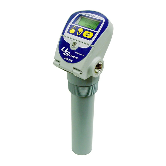
- Page 1 A Leader in Level Measurement Installation and Operating Instructions USonic™ Series Continuous Ultrasonic Level Transmitter using US-XX Series Electronics Telephone: +1 215-674-1234 Fax: +1 215-674-2731 E-mail: drexelbrook.service@ametek.com Website: www.drexelbrook.com...
- Page 2 AMETEK Drexelbrook makes no warranty of any kind with regard to the material contained in this manual, including, but not limited to, implied warranties or fitness for a particular purpose. Drexelbrook shall not be liable for errors contained herein or for incidental or consequential damages in connection with the performance or use of material.
- Page 3 EDO# 3-20-102 US-XX-LM Issue #11 USonic™ Series Continuous Ultrasonic Level Transmitter using US-XX Series Electronics...
-
Page 5: Table Of Contents
Table of Contents Glossary of Terms ........................... vi Quick Start Menu ........................... viii Section 1: Introduction ........................1 Product Description ......................1 Models Available ........................1 Approvals: (See Section: 6.4 for Details) ................1 System Specifications: ......................2 Definition of Terms ....................... 2 Types of Output ........................ -
Page 6: Glossary Of Terms
USonic™ US-XX Series Glossary of Terms Distance The measured distance from the sensor face to the target. Distance Mode Output signal increases as the distance increases (reverse acting output) Distance to Zero Flow This is the “No Flow” condition in a flume or weir. It may be to the bottom of the flume/weir, or depending on the type of flume/weir the “no flow”... - Page 7 Glossery of Terms Glossary of Terms Max Flow This is the maximum flow rate that is expected in a specific flume or weir. This is not necessarily the maximum flow that the flume/weir is capable of producing. Maximum Capacity Used in level to volume conversions, the maximum capacity of the vessel at a known maximum level point.
-
Page 8: Quick Start Menu
USonic™ US-XX Series Quick Start Menu Menu Navigation: 1. Hold ENTER Button 5 seconds to access configuration menu. 2. Use UP & DOWN buttons to select menu items 3. Press ENTER button to change selected items 4. Hold ENTER button to go to previous menu or continue to hold to return to operate mode. - Page 9 Glossery of Terms Quick Start Menu 5.05 Head Units Inches / Feet / Meters / Centimeters / Millimeters 5.06 Distance to Zero User Defined Numeric Value 5.07 Sensor Offset User Defined Numeric Value (Used Only With Custom Flumes) 5.08 Totalizer Scale X1 / X10 / X100 / X1k / X10k / X100k / X1Mil 5.09 Reset Totalizer?
- Page 10 USonic™ US-XX Series Quick Start Menu PRIMARY DEVICE CODES PARSHALL TRAPEZOIDAL FLUME PALMER BOWLUS CODE THROAT CODE SIZE CODE SIZE (IN) (IN) SMALL 60 DEG16 LARGE 60 DEG X-LARGE 60 DEG 3 FT 60 DEG 2 IN 45 DEG WSC 12 IN 45 DEG SRCRC 24 SRCRC H - FLUME...
-
Page 11: Section 1: Introduction
Introduction Section 1: Introduction Product Description The AMETEK Drexelbrook® USonic™ Series instrument is a Two- Wire (Integral) assembly. Using ultrasonic technology, the USonic™ continuously and accurately measures Level up to a range of 30 feet, or Open Channel Flow. The measurement output is a 4-20 mA current signal or HART®... -
Page 12: System Specifications
USonic™ US-XX Series System Specifications: • Power: 19 to 30 Vdc • Output: 2-Wire, 4-20 mA, HART • Sensor: 6.5” CPVC sensor rated: -40°F to +160°F (-40°C to +71°C) • Sensor Mounting: 2” NPT or 2” BSP, CPVC • Display Option: 2-Line, 7 digit LCD •... -
Page 13: Types Of Output
Introduction Definition of Terms (Continued) Sensor Offset: Sensor Offset is used to tell the transmitter the amount of distance above or below the top of the tank that the transducer face is located in order to calculate the tank volume. Sensor Offset can be applied in cases where: •... -
Page 14: Types Of Flumes And Weirs
USonic™ US-XX Series Types of Flumes and Weirs The USonic™ Supports the Following Flumes and Weirs: Leopold-Lagco Flumes (Variable Sizes): Flume Diameter (D) - Page 15 Introduction Types of Flumes and Weirs (Continued) “H” Flumes: Code Inches Millimeters 1372 Measuring Point Plan Flume Size Front...
- Page 16 USonic™ US-XX Series Types of Flumes and Weirs (Continued) Palmer Bowlus Flumes: Code Inches Millimeters Conduit Diameter (D) Throat...
- Page 17 Introduction Types of Flumes and Weirs (Continued) Trapezoidal (Cipolletti ) Weir (Variable Sizes): Trapezoidal (Cipolletti ) Flume: Code Size Small 60° V Large 60° V X Large 60° V 3 ft 60° V 2 in 45° WSC 12 in 45° SRCRC 24 in SRCRC H max...
- Page 18 USonic™ US-XX Series Types of Flumes and Weirs (Continued) V-Notch Weirs: Code Size 22.5° 30° 45° 60° 90° 120° V-Notch Angleº H max min. 3-4 H max...
- Page 19 Introduction Types of Flumes and Weirs (Continued) Crest Length Rectangular Weirs (Variable Sizes): Rectangular Weir with End Contractions FLOW Crest Length Crest Length min. 3-4 H max H max Rectangular Weir without End Contractions FLOW Crest Length min. 3-4 H max min.
- Page 20 USonic™ US-XX Series Types of Flumes and Weirs (Continued) Parshall Flumes: Code Inches Millimeters 1219 1524 1829 2438 2/3 Z...
-
Page 21: Section 2: Installation
Installation Section 2: Installation Unpacking Carefully remove the contents of the shipping carton and check each item against the packing list before destroying any packing material. If there is any shortage or damage, report it to the factory immediately. Mounting the Transmitter The USonic transmitter is available only as an integral construction. - Page 22 USonic™ US-XX Series Mounting the Transmitter (Continued) The USonic Series transmitter is designed for field mounting, but it should be mounted in a location as free as possible from vibration, corrosive atmospheres, and any possibility of mechanical damage. For convenience when adjusting and configuring, place the USonic Series in a reasonably accessible location.
-
Page 23: Wiring The Transmitter
Installation Wiring the Transmitter WARNING! If the USonic Series transmitter is located in a hazardous environment, do not open the enclosure cover or make / break any electrical connections without first disconnecting electrical power at the source. Ensure that wiring, electrical fittings and conduit connections conform to electrical codes and Approval Agency Control Drawings for specific location and environment. -
Page 24: Installation Examples
USonic™ US-XX Series Installation Examples 10 ft 10 ft (3.1m) (3.1m) 30 ft 10.5 in 10.5 in (914cm) 30 ft (27cm) (27cm) (914 cm) 1 ft 31.5 in 31.5 inches (80 cm) (80 cm) When there are no obstructions within Smooth wall in beam with no other the beam area, there is no chance of obstructions will not cause false echoes. - Page 25 Installation Installation Examples (Continued) Preferred Preferred Location Location When mounted off center in conical When mounted off center in conical bottom tanks, reflected echoes can be bottom tanks, reflected echoes can redirected back to the transducer. Use reflect away from the transducer in the 300ms, 700ms, 1100ms, or 1500 ms conical bottom resulting in a lost echo.
- Page 26 USonic™ US-XX Series Installation Examples (Continued) Use standard electronics with high Beam discrimination Angle setting. greater than inches Agitators within the beam path Mounted close to a wall or obstructions are present. Ability to ignore obstructions will depend on the exact size and location of the obstructions.
-
Page 27: Section 3: Configuration
Configuration Section 3: Configuration System Configuration with Display / Keypad The USonic system configuration is made up of 9 separate Functions (Fct.) for system and application set-up per the following: Input Type: Function 1.0 allows the user to select an appropriate "Input Type" for the application. -
Page 28: Configuration Menu
USonic™ US-XX Series Configuration Menu To enter the Configuration Menu: • Press and Hold the "Enter" Button for approximately 5 seconds. • Use the "Up" and "Down" Buttons to scroll through the available menu selections. • Press "Enter" to access sub-menu items. •... - Page 29 Configuration Menu Functions (Continued) Function Item Description & comment Menu Selection Choices Fct. 3.01 Distance Units User selects the units of measurement by "editing" the FEET (UNITS) menu to select either Feet, Inches, Meters, Centimeters, INCHES of Millimeters METERS CENTIMETERS MILLIMETERS Fct.
- Page 30 USonic™ US-XX Series Menu Functions (Continued) Function Item Description & comment Menu Selection Choices Fct. 4.07 Maximum Allows user to enter the volume of the vessels maximum Enter maximum capacity in vessel Capacity capacity that correlates to the Tank Height level. units selected.
- Page 31 Configuration Menu Functions (Continued) Function Item Description & comment Menu Selection Choices Fct. 6.00 Strapping Allows the system configuration for the strapping Table table. Enabled when Flow or Volume is selected (STRAP) in Fct. 1.01. The strapping table is a look-up table of level vs.
- Page 32 USonic™ US-XX Series Menu Functions (Continued) Function Item Description & comment Menu Selection Choices Fct. 7.08 Lost Echo Fault If the echo is not returned to the sensor, the user can, HIGH (22 mA) (LE OUT) in this menu item select the current level the analog LOW (3.7 mA) signal will assume (3.7 mA or 22 mA) during a fault LST VAL...
- Page 33 Configuration Menu Functions (Continued) Function Item Description & comment Menu Selection Choices Fct. 7.20 Pipe Length This item allows the user to enter the length of the 0 (Edit length in level Units), - for (PIPE_L) pipe in which the USonic is installed. open air (no pipe) use 0 Fct.
-
Page 34: Error Messages
USonic™ US-XX Series Error Messages ... . Lost Echo ... . Near Zone . . Communications Error Between Display and Transmitter . -
Page 35: Section 4: Troubleshooting
Troubleshooting Section 4: Troubleshooting The USonic™ Series Ultrasonic Level system is designed to give years of unattended service. No periodic or scheduled maintenance is required. Troubleshooting Procedures If a problem should occur with the operation of the transmitter, use the following procedure for troubleshooting. -
Page 36: Optimized Field Calibration
USonic™ US-XX Series Optimized Field Calibration Configuration Menu Function 9.01 allows a 1-Point calibration based on a known actual distance. This can adjust for any possible variations that may exist in the speed of sound, or to provide an optimized calibration data point in difficult applications. -
Page 37: Diagnostic Messages
Troubleshooting Troubleshooting the Loop Connections (Continued) Check: 1. If current is greater than 22 mA disconnect at sensing Start element and re-check. Is loop 2. If loop current is 0 mA, check polarity of loop at Modem does current transmitter. If it is OK, check for open loop. between 3.7 and 3. -
Page 38: Telephone Assistance
USonic™ US-XX Series Telephone Assistance If you have questions about your AMETEK Drexelbrook equipment: • Contact your local Drexelbrook representative • Call the Drexelbrook Service department toll-free at: 215-674-1234 • Fax the following information to the Service department at: 215-443-5117. -
Page 39: Field Service
205 Keith Valley Road Horsham, PA 19044 COD shipments will not be accepted. AMETEK Drexelbrook warrants its products free of material defects or manufacturing defects for a period of 1 year after date of shipment. Field Service Trained field service personnel are available on a time-plus-expense basis to assist in start-ups, diagnosing difficult application or equipment problems, or in-plant training of personnel. - Page 40 Section 5:...
-
Page 41: Section 5: Configuration And Calibration With Hartwin
Configuration and Calibration Section 5: Configuration and Calibration With HARTWin™ This section instructs the user how to use the Drexelbrook 401-700-20/40 Series PC calibrator software to configure and calibrate the USonic™ Transmitter. General Description The 401-700-20/40 software package allows the use of any Windows® 9X/NT/2000/XP-based personal, laptop, or notebook computer to calibrate the HART... -
Page 42: Installing The Rs232 Modem
USonic™ US-XX Series Installing The RS232 Modem Refer to Figure 5-1 for a connection diagram and use the following procedure to install the hardware that is necessary to run the PC software. 1. Connect the RS232 Drexelbrook Modem 401-700-004 to one of the COM serial ports (COM1, COM2, etc.) of the computer. -
Page 43: Installing The Usb Modem
Configuration and Calibration Installing The USB Modem Refer to Figure 5-1a for a connection diagram and use the following procedure to install the hardware that is necessary to run the PC software. 1. Turn on the computer 2. Install Modem Software: It is highly recommended the USB drivers be installed BEFORE you plug in the modem. -
Page 44: Install The Windows Version Hartwin™ Software On Hard Drive
USonic™ US-XX Series Install the Windows Version HARTWin™ Software on Hard Drive Installation is simple. 1. Place the 401-700-031 CD into the CD drive (usually drive D:). 2. If program does not "Auto-Run", select "D:\setup" (where D is the letter representing the CD Drive). 3. -
Page 45: Description Of Function Keys
Configuration and Calibration Description of Function Keys Figure 5-3 HARTWin™ Function Keys HARTWin™ automatically communicates all "Name Plate Data" from the transmitter The following paragraphs describe the function buttons. The data fields are described in Section 3.7- Configuration. Read Transmitter [F3 on keyboard] Reads all pertinent data from the transmitter and displays it on the screen. -
Page 46: Configuration
USonic™ US-XX Series Configuration Configuration involves uploading information to the transmitter that is specific to the application being measured. Ex. Flow, Level, Distance, or Volume. Figure 5-4 Selecting Configuration 1. Begin configuration by using Tag ID (8 characters) or Long Tag (32 characters) to identify the unit or vessel. - Page 47 Configuration and Calibration 5.8.1 Level Configuration Figure 5-5 Level Configuration Menu 1. Select Level Units. The default is Inches. Choose the units that correspond to the level measurement. 2. Edit the Tank Height to agree with the actual tank height (not the length of the sensing element).
- Page 48 USonic™ US-XX Series 5.8.1 Level Configuration (Continued) Sensor Offset can be applied in cases where: • The transducer protrudes below the top of the tank or, • The transducer is mounted above the top of the tank or, • A pipe extension is installed to raise the transducer face 12 inches above the tank height to compensate for the 12-Inch Near Zone.
- Page 49 Configuration and Calibration 5.8.2 Distance Configuration Figure 5-6 Distance Configuration Menu 1. Select Distance Units. The default is Inches. Press Enter and Choose the units that correspond to the Distance Measurement. 2. Choose Write to Transmitter.
- Page 50 USonic™ US-XX Series 5.8.3 Volume Configuration Figure 5-7 Volume Configuration Menu 1. Select Volume Units .The default is gallons. Press Enter and choose the units that correspond to the volume measurement. Default selection is gallons . Press Tab or Enter. 2.
- Page 51 Configuration and Calibration 5.8.4 Flow Configuration Figure 5-8 Flow Configuration Menu 1. Select Head Units. The default selection is Inches. 2. Enter Distance to Zero (The value that defines the distance from the Transducer Face to the bottom of the Flume / Weir at Zero Flow). This value also corresponds to the 4 mA (0% of Range) point.
- Page 52 USonic™ US-XX Series 5.8.4 Flow Configuration (Continued) Totalizer Configuration (Available Only when Flow Measurement is Selected) 1. Select Totalizer Scale Default value is x 100. Select the scale of the total flow to be displayed. 2. Reset the Totalizer This resets the second total flow. Select Field Device - Reset Total Flow in the HARTWin Menu.
- Page 53 Configuration and Calibration 5.8.5 LRV and URV (Continued) Entering LRV and URV in the Level Mode Example #1 Tank is 12 feet tall. Set Tank Height to 12 feet. LRV (4 mA point) is 0 feet (bottom of tank). URV (20 mA point) is 11 feet. (Bottom of tank to transducer face minus 12 inch near zone.) Example #2 Tank is 31 feet tall (one foot farther than range of transmitter).
- Page 54 USonic™ US-XX Series 5.8.6 Ultrasonic Configuration Figure 5-11 Ultrasonic Configuration Menu Repetition Rate An application might require a longer repetition rate, depending on the type of vessel and material being measured. For instance: • Increasing the repetition rate to 400 ms is required any time that the tank roof is curved.
- Page 55 Configuration and Calibration 5.8.6 Ultrasonic Configuration (Continued) Gain Select the gain setting for the ultrasonic instrument. HD (High Discrimination) • High discrimination mode automatically reduces the effect of nuisance echos created when mounting the transducer in a nozzle or mounting the transducer inside a pipe up to 14 inches above the tank opening.
- Page 56 USonic™ US-XX Series 5.8.7 Point Calibration Point calibration increases the accuracy of the measurement and compensates for atmospheres other than air by using the actual distance to the Transducer Face for calibration. Figure 5-12 Point Calibration Menu 1. Measure the distance from the Transducer Face to the surface of the material being measured.
- Page 57 Configuration and Calibration 5.8.8 Configure Meter The 7-Digit Display can be configured to display Status Messages and any Calculated Value. (4-20 mA, % of Range, Distance, Temp., etc. ) The Configure Meter Function allows the user to select the values that can be viewed on the display.
- Page 58 USonic™ US-XX Series 5.8.8 Configure Meter (Continued) Password Configuration Password Enabled This Enables or Disables the Password Required to enter the Menu. Password 1-7 This selects the keypad sequence values of the password to enter the menu on the display. Password 1 is the value for the first keypress.
- Page 59 Configuration and Calibration 5.8.9 Strapping Table The Strapping Table is a 2-21 Point, table used to create a Custom non- linear output relationship to Level or Head Height. Flow Applications Several pre-defined Flume / Weir types are available See Section 5.8.4. If none of the pre-defined Flume / Weir types are appropriate for the application, a Custom Strapping Table will be necessary.
- Page 60 USonic™ US-XX Series 5.8.9 Strapping Table (Continued) Plan your table by filling out the table below. • Use the first column which lists every 5% between 0 and 100% Fill in your own values in column 2. • Fill out column 3 with output values corresponding to those listed in column 1 or 2.
-
Page 61: Section 6: System Specifications
Specifications Section 6: System Specifications Transmitter Specifications Power Requirement: 12.0 to 30 Vdc - Voltages in excess of 30 Vdc will cause permanent damage. Load Resistance = V supply – 12.0 / 0.02 • Minimum supply voltage is 19 volts at 4 mA •... -
Page 62: Transducer Specifications
USonic™ US-XX Series Transducer Specifications Sensor Material: CPVC Pressure: -10 to 50 psig 2" NPT / BSP Process Connection Operating Temperature: -40 to 158°F (-40°C to 70°C) Beam Angle: Conical, 10° typical, at the 3 db down point Enclosure Specifications PBT-RF (Valox 420 SEO UV Stabilized) to NEMA 4X (IP 66) US - 1X 3/2"... - Page 63 Specifications Approvals (Continued) IECEx Ex ia IIC T5 FMG05.0001X IEC – 60079 – 0 – General Requirements 2011 IEC – 60079 – 11 – Intrinsic Safety 2011 IEC 60079-26 - Equipment with Equipment Protection Level (EPL) 2006 Install per 420-0004-418-CD ATEX II 1 G Ex ia IIC T5 US2X - IP66, IP68 Presafe 15 ATEX 6243X...
- Page 64 USonic™ US-XX Series Approvals (Continued) US23, ATEX Label US22, FM Label...
-
Page 65: Section 7: Control Drawings / General Safety Information
Control Drawings Section 7: Control Drawings / General Safety Information General Safety Information This document contains installation instructions for potentially explosive atmosphere applications. The USonic is approved for use in hazardous locations when properly installed. Control drawings detailing installation guidelines are available in this section. - Page 66 USonic™ US-XX Series General Safety Information (Continued) 7.1.3 Explosionproof or Flameproof Installations (Model US2) No Live maintenance is permitted. Disconnect power to the device and check that the atmosphere is clear of hazardous substances. 7.1.4 Start-up checklist Do not connect power until you have gone through the checklist below 1.
-
Page 67: 2X Fm/Fmc Control Drawing
Control Drawings FM Control Drawings... - Page 68 USonic™ US-XX Series FM Control Drawings (Continued)
- Page 69 Control Drawings FM Control Drawings (Continued)
-
Page 70: 1X Fm/Fmc Control Drawing
USonic™ US-XX Series FMc Control Drawings... - Page 71 Control Drawings FMc Control Drawings (Continued)
- Page 72 USonic™ US-XX Series FMc Control Drawings (Continued)
-
Page 73: Atex Control Drawing
Control Drawings ATEX Control Drawings... - Page 74 AMETEK, Inc. TERMS AND CONDITIONS OF SALE THE FOLLOWING TERMS/CONDITIONS, TOGETHER WITH ANY OTHER TERMS/CONDITIONS SPECIFICALLY AGREED TO IN WRITING BY SELLER, SHALL APPLY TO ALL ORDERS (“Order(s)”) FROM, AND SALES OF PRODUCTS (“Products”) OR SERVICES (“Services”) TO BUYER. ANY ACCEPTANCE OF ANY ORDER OF BUYER IS CONDITIONED UPON THESE TERMS/CONDITIONS. ANY ADDITIONAL OR DIFFERENT TERMS/CONDITIONS PROPOSED BY BUYER IN ANY DOCUMENT ARE OBJECTED TO AND SHALL NOT BE BINDING UPON SELLER.
- Page 75 WHETHER ORAL, WRITTEN, EXPRESS, IMPLIED OR STATUTORY. Seller’s prior written consent. Upon completion of Order, Buyer shall promptly return all Data to Seller together with all copies or reprints thereof NO IMPLIED OR STATUTORY WARRANTIES OF then in Buyer's possession or control, and Buyer shall thereafter make no MERCHANTABILITY OR FITNESS FOR PARTICULAR PURPOSE future use, either directly or indirectly, of any Data or any information SHALL APPLY.
- Page 76 205 Keith Valley Road, Horsham, PA 19044 Telephone: +1 215-674-1234 Fax: +1 215-674-2731 E-mail: drexelbrook.info@ametek.com An ISO 9001 Certified Company Website: www.drexelbrook.com...
Need help?
Do you have a question about the USonic Series and is the answer not in the manual?
Questions and answers