
Related Manuals for Alpha Technologies EDSM


Summary of Contents for Alpha Technologies EDSM
- Page 1 EDSM Enhanced Digital Status Module Technical Manual Enhanced Digital Status Module Effective: May 2008 Alpha Technologies...
- Page 2 Power Alpha Technologies ®...
- Page 3 NOTE: Operator is cautioned to review the drawings and illustrations contained in this manual before proceeding. If there are questions regarding the safe operation of this powering system, please contact Alpha Technologies or your nearest Alpha representative. NOTE:...
-
Page 4: Table Of Contents
Table of Contents Safety Notes .......................... 6 Introduction ......................... 8 System Layout ....................9 Connectors and Indicators ..................10 LED Indicators ....................10 STAT Switch ....................11 COM Connector ..................... 12 Tamper Connector ..................13 DIP Switch ..................... 14 Headers ......................15 Module Installation .................... - Page 5 Fig. 2-5, DIP Switch Location ....................14 Fig. 2-6, Headers ......................... 15 Fig. 3-1, Ribbon Cable Removal ..................16 Fig. 3-2, EDSM Details ......................17 Fig. 3-3, Device Interconnection ..................18 Table 2-1, Alarm Codes ......................11 Table 2-2, DIP Switch Settings .................... 14 Table 3-1, Troubleshooting ....................
-
Page 6: Safety Notes
Safety Notes Review the drawings and illustrations contained in this manual before proceeding. If there are any questions regarding the safe installation or operation of this product, contact Alpha Technologies or the nearest Alpha representative. Save this document for future reference. - Page 7 General Safety Precautions To avoid injury: • This enclosure and its associated hardware must be serviced only by authorized personnel. • Enclosure must remain locked at all times, except when authorized service personnel are present. • Remove all conductive jewelry or personal equipment prior to servicing equipment, parts, connectors, wiring, or batteries.
-
Page 8: Introduction
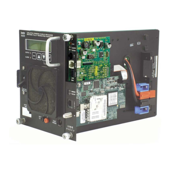
Alpha’s Enhanced Digital Status Module (EDSM) is a status monitoring interface for the XM Series 2 power supply. The EDSM can monitor up to six power supplies and an AlphaGen generator. Up to two battery strings can be monitored directly using the AUX connector and applicable wiring harness. -
Page 9: System Layout
EDSM can monitor up to six (6) power supplies, two battery strings via the AUX connector, and one (1) generator. The EDSM collects data from these devices and relays it to the head end using a digital transponder. -
Page 10: Connectors And Indicators
LED is only turned off while alarm codes are being displayed. The green DT LED indicates active communications between the EDSM and the DT. It is an indication of receive activity of the serial communications between the EDSM and DT. -
Page 11: Stat Switch
No temp probes found. Confi guration Error XM2 has confi guration error. DT/COM Some XM2s see line, others do not. ALM/RDY EDSM failed self-test on initial power up. Self Test Fail DT/COM ALM/RDY Daughter board Battery Sense is missing Daughter Board Status or failed. -
Page 12: Com Connector
CAUTION! The DT connector is only used for connecting to an external digital transponder. Connecting any other device to the DT connector may result in damage to the EDSM, associated equipment, and errantly connected device (i.e. laptop). 704-721-C0-004, Rev. D... -
Page 13: Tamper Connector
Connectors and Indicators, continued AUX and Tamper Connectors The AUX connector allows the EDSM to monitor two 36Vdc or 48Vdc battery strings. The TAMPER connector is used for cabinet door detection. Tamper switches are wired in parallel and connected at this location. The pin numbering and description are shown below:... -
Page 14: Dip Switch
Vcc and ground of the equipment. The programming mode switch setting is used during programing of the micro controller. SW4 MUST be in the OFF position for normal operation of the EDSM. For most transponders, SW3 must be in the ON position. Switch # Position Description... -
Page 15: Headers
The OEM Embedded Transponder (OEMET) connector is located in the lower right hand corner of the circuit board and uses a 2x5 ribbon cable connector. The connector is used for connecting the EDSM to a digital transponder. Example OEMET include: Tollgrade Docsis Embedded Transponder, Tollgrade HMS Embedded Transponder, AM HMS Embedded Transponder, WISI HMS Embedded Transponder, Tollgrade Proprietary Embedded Transponder, and AM Proprietary Embedded Transponder. -
Page 16: Module Installation
3.0 Module Installation NOTE: • If the XMS2 system already has an existing comm module installed, remove the module as outlined in the procedure below. If the system does not have a communications module installed, proceed to the next section for the installation procedure. •... - Page 17 9. Verify that the 2x9 pin jumper is in position, seated fully into the inverter module. 10. Align the XMS2 header on the EDSM with the 2x9 jumper and gently press into place. 11. Tighten the captive mounting screws into the inverter module.
- Page 18 ON position. 16. Reconnect all other cables and sensors. 17. Connect devices to the EDSM as shown below. 18. Verify and program if necessary all XMS2 power supplies to a unique address (1 through 7) via the XM2 (refer to XM2 Technical Manual Smart Display Set Up Menu). Refer to the AlphaGuard manual for CMM hookup.
- Page 19 XMS2 Communication Module Removal Procedure, continued 19. Press and hold the STAT push-button on the front panel of the EDSM until all LEDs go out, continue to press the button until the RDY LED is lit indicating that the reset function is initiated.
- Page 21 Tel: +33 32 64990 54 Fax: +33 32 64990 54 Due to continuing product improvements, Alpha reserves the right to change specifi cations without notice. Copyright © 2008 Alpha Technologies, Inc. All rights reserved. Alpha is a registered trademark of Alpha Technologies. 704-721-C0-004, Rev.D.
Need help?
Do you have a question about the EDSM and is the answer not in the manual?
Questions and answers