
Subscribe to Our Youtube Channel
Related Manuals for Alpha Technologies Cordex 24


Summary of Contents for Alpha Technologies Cordex 24
- Page 1 Cordex 24-400W ® Rectifier Shelf System Technical Guide: 9400021-J0 Effective: 07/2020...
- Page 3 Copyright Copyright © 2020 Alpha Technologies Ltd. All rights reserved. Alpha is a registered trademark of Alpha Technologies. No part of this documentation shall be reproduced, stored in a retrieval system, translated, transcribed, or transmitted in any form or by any means manual, electric, electronic, electromechanical, chemical, optical, or other-wise without prior explicit written permission from Alpha Technologies.
-
Page 5: Table Of Contents
Contents List of Figures............................... 4 List of Tables..............................5 1. Safety............................... 6 2. Introduction............................. 9 2.1. Scope..............................9 2.2. Product Overview........................... 9 3. Features..............................11 3.1. Rectifier............................11 3.2. Overview of the CXCi HP......................14 3.3. Overview of the CXCi+........................ 16 3.4. Controller Input and Output......................18 4. - Page 6 11. Certification............................40 12. Glossary...............................41 13. Specifications............................43 13.1. 2RU, 24-400W, 19", 4 Module System..................43 13.2. 2RU, 24-400W, 19", 5 Module System..................44 13.3. Cordex 24-400W Switched Mode Rectifier................45 13.4. CXCi HP Controller........................48 13.5. CXCi+ Controller........................50 9400021-J0 Rev B Page 3...
-
Page 7: List Of Figures
Cordex® 24-400W 19” Integrated Shelf Installation and Operations Guide List of Figures Figure 1: Four Module System, 030-763-20-XXX..................10 Figure 2: Five Module System, 030-773-20-XXX..................10 Figure 3: Rectifier Front Panel........................11 Figure 4: CXCi HP Controller........................14 Figure 5: In-Shelf Controller Dashboard Screens..................15 Figure 6: In-Shelf Controller Menu......................15 Figure 7: In-Shelf Controller Buttons......................16 Figure 8: Cordex CXCi+ model system controller front panel.............. -
Page 8: List Of Tables
Table 8: Sample Maintenance Log......................36 Table 9: Specifications: 24-400W 19", 4 Module System................43 Table 10: Specifications: 24-400W 19”, 5 Module System................ 44 Table 11: Specifications: Cordex 24-400W, Switched Mode Rectifier............45 Table 12: Specifications: CXCi HP Controller.................... 48 Table 13: Specifications: CXCi+ Controller....................50... -
Page 9: Safety
Keep it in a safe place. Review the drawings and illustrations contained in this manual before proceeding. If there are any questions regarding the safe installation or operation of this product, contact Alpha Technologies or the nearest Alpha representative. - Page 10 Cordex® 24-400W 19” Integrated Shelf Installation and Operations Guide | 1 - Safety • Remove all metallic jewelry, such as watches, rings, metal rimmed glasses, or necklaces. • Wear safety glasses with side shields at all times during the installation. •...
- Page 11 Cordex® 24-400W 19” Integrated Shelf Installation and Operations Guide | 1 - Safety unit with batteries installed may cause a short circuit, fire, explosion, and/or damage to the battery pack, enclosure and installed equipment. • Servicing and connection of batteries must be performed by, or under the direct supervision of, personnel knowledgeable of batteries and the required safety precautions.
-
Page 12: Introduction
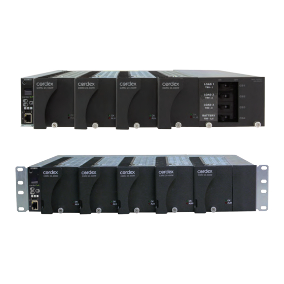
2. Introduction 2.1. Scope This manual explains the installation, interconnection, and operation of the following Alpha Technologies shelf systems: ® • Cordex 24-400W integrated 19" 2RU shelf system with up to 1600W output power and distribution. ® • Cordex 24-400W integrated 19" 2RU shelf system with up to 2000W bulk output power. -
Page 13: Figure 1: Four Module System, 030-763-20-Xxx
Cordex® 24-400W 19” Integrated Shelf Installation and Operations Guide | 2 - Introduction Figure 1. Four Module System, 030-763-20-XXX Figure 2. Five Module System, 030-773-20-XXX Page 10 9400021-J0 Rev B... -
Page 14: Features
3. Features 3.1. Rectifier ® The Cordex CXRC series of 24V 400W rectifier modules employ an advanced resonant power conversion technology featuring high power conversion efficiency. All internal semiconductor devices operate under “soft-switching” conditions and exhibit very low power loss. The reduced power loss leads to lower thermal stress on the semiconductors and thus improves reliability. - Page 15 Cordex® 24-400W 19” Integrated Shelf Installation and Operations Guide | 3 - Features Alarm The bottom LED (red) is on continuously in the event of an active Module Fail alarm. The LED flashes (~2Hz) when a minor alarm is detected. The LED remains off in the absence of an alarm. LED Activity During “Locate Module”...
- Page 16 Cordex® 24-400W 19” Integrated Shelf Installation and Operations Guide | 3 - Features Wide AC Range A minor alarm is generated when the AC input voltage drops below specification. The unit will deliver derated output power down to 60Vac. • Note: Output power is reduced linearly between 90Vac to 60Vac to 0% of the rated output power.
-
Page 17: Overview Of The Cxci Hp
Cordex® 24-400W 19” Integrated Shelf Installation and Operations Guide | 3 - Features High Voltage Shutdown (HVSD) This feature provides protection to the load from over voltage conditions originating from the rectifiers. It operates by shutting down the offending rectifier module when a high output voltage condition occurs. Indication is through the red Alarm (Module Fail) LED. -
Page 18: Figure 5: In-Shelf Controller Dashboard Screens
Cordex® 24-400W 19” Integrated Shelf Installation and Operations Guide | 3 - Features The following figure below shows examples of the screens. Figure 5. In-Shelf Controller Dashboard Screens D C - - 4 8 5 4 . 0 9 V Output Voltage 1 0 3 . -
Page 19: Overview Of The Cxci
Cordex® 24-400W 19” Integrated Shelf Installation and Operations Guide | 3 - Features Table 1. In-Shelf Controller Full Menu (continued) Menu Label Description Backup Backup the controller application and configuration to a file on a USB device Restore Restore the controller application and configuration from a file on a USB device Upgra... -
Page 20: Figure 8: Cordex Cxci+ Model System Controller Front Panel
Cordex® 24-400W 19” Integrated Shelf Installation and Operations Guide | 3 - Features Figure 8. Cordex CXCi+ model system controller front panel System Status LEDs LCD Screen Display Mode: pushbutton toggle switch Hard Reset (push once) Soft Reset (push once) Hold for three seconds to reset IP address Ethernet Port... -
Page 21: Controller Input And Output
Cordex® 24-400W 19” Integrated Shelf Installation and Operations Guide | 3 - Features the front panel. A full defragmentation may take up to 20 minutes to perform, do not power down the controller during this time. Note: Refer also to the software manual – always select the Reset menu item before pressing the reset button. - Page 22 Cordex® 24-400W 19” Integrated Shelf Installation and Operations Guide | 3 - Features Network Connection and Remote Communication ® The Cordex system can be set up, monitored and tested via an Ethernet connection. The communication protocol supports a web interface. All alarming and control of the rectifiers is accomplished with a controller via a CAN bus.
-
Page 23: Inspection
Alpha Technologies is not responsible for damage caused by improper packaging of returned products. If you have any questions before you proceed, call Alpha Technologies: 1 888 462-7487. -
Page 24: Installation
5. Installation This chapter is provided for qualified personnel to install the product. Mount the unit horizontally in a clean and dry environment. Note: Drawings are located at the rear of the manual. Warning: This system is designed to be installed in a restricted access location that is inaccessible to the general public. -
Page 25: Module Insertion And Removal
Cordex® 24-400W 19” Integrated Shelf Installation and Operations Guide | 5 - Installation 5.3. Module Insertion and Removal The rectifier is plug and play. When a rectifier module is added to the system, the controller will detect and update the inventory automatically. Replacing an installed rectifier requires a manual Inventory Update at the controller to clear the removed rectifier from its current list of rectifiers. - Page 26 Cordex® 24-400W 19” Integrated Shelf Installation and Operations Guide | 5 - Installation Remove controller mounting screws 3. Pull from the location noted in the following image to remove the controller. Pull here to remove the controller from the shelf CAUTION: When removing the controller in a live system that has an LVD, ensure that the LVD override jumper is set to correct position to avoid possible service disruption.
-
Page 27: Wiring And Connections
6. Wiring and Connections 6.1. Safety Precautions Warning: Hazardous AC voltages may be present. Ensure power at the AC service panel is off before attempting work on the AC connections. Use a voltmeter to verify the absence of voltage. Clearly mark the correct polarity of the battery leads before commencing work on DC connections. -
Page 28: Ac Input
Cordex® 24-400W 19” Integrated Shelf Installation and Operations Guide | 6 - Wiring and Connections It is recommended, for each feed, to use a dedicated protection feeder breaker located at the AC distribution panel. The feeder breaker can also act as the disconnect device for the connected modules. Table 2. -
Page 29: Dc Output
Cordex® 24-400W 19” Integrated Shelf Installation and Operations Guide | 6 - Wiring and Connections Check again that the ampacity rating of the cable meets the requirement for the installation application. Consult local electrical codes (NEC, CEC, etc.) for guidelines. If required, increase the size of the cable to meet the code. -
Page 30: Can Ports
Cordex® 24-400W 19” Integrated Shelf Installation and Operations Guide | 6 - Wiring and Connections 6.8. CAN Ports Four Module shelf: one CAN OUT port located at the rear of the shelf. Five Module shelf: one CAN IN and one CAN OUT port. Located at the back of the shelf. Daisy-chain from node to node (CAN OUT of one node to CAN IN of another) as necessary and ensure that only the last node is terminated. - Page 31 Cordex® 24-400W 19” Integrated Shelf Installation and Operations Guide | 6 - Wiring and Connections Table 3. Wiring Connections for the CXCi Series of Controllers (continued) Terminal Description Default Name Signal Type Range 7, 8, 9* Alarm Output 3 K3, Relay 3 NO/COM/NC 60VDC / 1A 10, 11, 12*...
-
Page 32: Figure 10: Digital Input Connection Method
Cordex® 24-400W 19” Integrated Shelf Installation and Operations Guide | 6 - Wiring and Connections Current input #1 is wired internally to the system current shunt for shelves with integrated distribution, and wired to an external shunt for bulk distribution shelves. Temperature Sensor Temperature Probe input channels provide connections for up to two temperature sensors. -
Page 33: Figure 11: Relay Connections
Cordex® 24-400W 19” Integrated Shelf Installation and Operations Guide | 6 - Wiring and Connections Table 4. Voltage Level Definitions for Digital Inputs Voltage Level (Vdc), Voltage Level (Vdc), Considered As “0” (Off) Considered As “1” (On) 0 - 60 (System Voltage Setting) 0 to 3V 9 to 60V Alarm Relay Outputs... -
Page 34: Operation
7. Operation 7.1. Main Rectifier States Rectifier operation has five main states; each state is distinct and necessary for the operation of the rectifier. • Off • Start Delay • Soft Start • Normal Operation • Turning Off The rectifier is in the Off state immediately after power is applied to the rectifier or after a rectifier shutdown (remote or local shutdown, AC shutdown, OVP or thermal shutdown). -
Page 35: Main Rectifier Modes
Cordex® 24-400W 19” Integrated Shelf Installation and Operations Guide | 7 - Operation Turning Off The Turning Off state is entered because a short delay is required before the rectifier actually turns off to take care of any initialization requirements. When this short delay has elapsed, a transition to the Off state is made. -
Page 36: Can Bus Communication
Cordex® 24-400W 19” Integrated Shelf Installation and Operations Guide | 7 - Operation 7.3. CAN Bus Communication The CAN bus is used for commands and data transfer between the rectifier and controller to configure the rectifier with system settings and to monitor rectifier status. 7.4. -
Page 37: System Startup
8. System Startup 8.1. Check System Connections • Ensure AC is off, battery is disconnected, and all power modules are removed from the shelf. • Verify the polarity of all connections. 8.2. Verify AC and Power the Shelf • Install one power module. •... -
Page 38: Controller Reset - Cxci Hp
Cordex® 24-400W 19” Integrated Shelf Installation and Operations Guide | 8 - System Startup IP Address Reset To reset the IP address, press and hold the front panel soft reset button for three seconds. The CXCi+ unit beeps three times, IP address resets to 10.10.10.201 and DHCP is disabled. The settings are saved and the unit then resets. -
Page 39: Maintenance
9. Maintenance Although very little maintenance is required with Alpha systems, routine checks and adjustments are recommended to ensure optimum system performance. Qualified service personnel should do repairs. The following table lists a few maintenance procedures for this system. These procedures should be performed at least once a year. - Page 40 Cordex® 24-400W 19” Integrated Shelf Installation and Operations Guide | 9 - Maintenance Customer Connection Board Detail TB12 15 16 BATT Used internally for LVD control (if equipped) NC C NO NC C NO NC C NO 12 11 10 9 TB11 See below for jumper settings...
-
Page 41: Replacing A Cxci Hp Controller
Cordex® 24-400W 19” Integrated Shelf Installation and Operations Guide | 9 - Maintenance 8. Use a meter to verify the bus voltage and current shunt. Recalibrate as required due to differences in the new CXCi+. 9. Replace rectifiers and remove LVD bypass. 9.2. -
Page 42: Warranty And Service Information
10. Warranty and Service Information Technical Support In Canada and the USA, call toll free 1-888-462-7487. Customers outside Canada and the USA, call +1-604-436-5547. Warranty Statement For full information details review Alpha's online Warranty Statement at www.alpha.ca. Product Warranty Alpha warrants that for a period of two (2) years from the date of shipment its products shall be free from defects under normal authorized use consistent with the product specifications and Alpha’s instructions, the terms of the manual will take precedence. -
Page 43: Certification
11. Certification CSA (Canadian Standards Association also known as CSA Group) was established in 1919 as an independent testing laboratory in Canada. CSA received its recognition as an NRTL (Nationally Recognized Testing Laboratory) in 1992 from OSHA (Occupational Safety and Health Administration) in the United States of America (Docket No. -
Page 44: Glossary
12. Glossary Alternating Current ACCT Alternating Current Current Transducer ADIO Analog-digital input-output Alarm An alarm has user configurable fields like a name, priority and it can is able to sent SNMP or email notifications when it becomes active or cleared ALCO Alarm cutoff Alert... - Page 45 Cordex® 24-400W 19” Integrated Shelf Installation and Operations Guide | 12 - Glossary Media Access Control; e.g. MAC address Management Information Base; a database of entities most often associated with SNMP Metal Oxide Varistor Multiplexer NEBS Network Equipment-Building System; a set of safety, spatial and environmental guidelines for telecom OLED Organic LED, in-shelf controller display...
-
Page 46: Specifications
13. Specifications 13.1. 2RU, 24-400W, 19", 4 Module System Table 9. Specifications: 24-400W 19", 4 Module System Specifications: 24-400W 19", 4 Module System Basic Unit: Shelf Maximum Output: 53A, 30VDC Recommended 20A, #12 AWG per feed Feed Breaker, Sin- gle Phase: Mechanical Dimensions: 88mm H x 444mm W x 307mm D, rectifier front panel 18mm D (3.5"... -
Page 47: 2Ru, 24-400W, 19", 5 Module System
Cordex® 24-400W 19” Integrated Shelf Installation and Operations Guide | 13 - Specifications 13.2. 2RU, 24-400W, 19", 5 Module System Table 10. Specifications: 24-400W 19”, 5 Module System Specifications: 24-400W 19", 5 Module System Basic Unit: Shelf Maximum Output: 67A, 30VDC Recommended 20A, #12 AWG per feed Feed Breaker, Sin-... -
Page 48: Cordex 24-400W Switched Mode Rectifier
Cordex® 24-400W 19” Integrated Shelf Installation and Operations Guide | 13 - Specifications 13.3. Cordex 24-400W Switched Mode Rectifier Table 11. Specifications: Cordex 24-400W, Switched Mode Rectifier Specifications: Cordex 24-400W, Switched Mode Rectifier Power Module Output Voltage: 21 to 30Vdc within rated limits... - Page 49 Cordex® 24-400W 19” Integrated Shelf Installation and Operations Guide | 13 - Specifications Table 11. Specifications: Cordex 24-400W, Switched Mode Rectifier (continued) Specifications: Cordex 24-400W, Switched Mode Rectifier Any changes or modifications to this equipment not expressly described in this manual could void the FCC compliance.
- Page 50 Cordex® 24-400W 19” Integrated Shelf Installation and Operations Guide | 13 - Specifications Table 11. Specifications: Cordex 24-400W, Switched Mode Rectifier (continued) Specifications: Cordex 24-400W, Switched Mode Rectifier Dimensions: 88.1mm H x 71.6mm W x 242mm D (excluding connector) [3.47" H x 2.82" W x 9.5"...
-
Page 51: Cxci Hp Controller
Cordex® 24-400W 19” Integrated Shelf Installation and Operations Guide | 13 - Specifications 13.4. CXCi HP Controller Table 12. Specifications: CXCi HP Controller Specifications: Basic Unit, CXCi HP Input Voltage: 12 to 60Vdc within rated limits Current: <200mA @ 52Vdc, <400mA @ 26.5Vdc, <800mA @ 13.2Vdc MTBF: 95,000 hours (10.9 years), with display off OLED 84,000 hours @ 10% usage, 9,800 atv100% usage, at 25°C... - Page 52 Cordex® 24-400W 19” Integrated Shelf Installation and Operations Guide | 13 - Specifications Table 12. Specifications: CXCi HP Controller (continued) Specifications: Basic Unit, CXCi HP Temperature: -40 to 65°C (-40 to 149°F) operating -40 to 80°C (-40 to 176°F) storage Humidity: 5% to 95% RH non-condensing Elevation:...
-
Page 53: Cxci+ Controller
Cordex® 24-400W 19” Integrated Shelf Installation and Operations Guide | 13 - Specifications 13.5. CXCi+ Controller Table 13. Specifications: CXCi+ Controller Specifications: Basic Unit, CXCi+ Input Voltage: 10 to 65Vdc within rated limits Current: <100mA @ 48Vdc <200mA @ 24Vdc MTBF: 1,500,000 hrs @30°C (86°F) ambient EMC:... - Page 54 Cordex® 24-400W 19” Integrated Shelf Installation and Operations Guide | 13 - Specifications Table 13. Specifications: CXCi+ Controller (continued) Specifications: Basic Unit, CXCi+ • Reorient or relocate the receiving antenna. • Increase the separation between the equipment and receiver. • Connect the equipment into an outlet on a circuit different from that to which the receiver is connected. •...
- Page 55 Cordex® 24-400W 19” Integrated Shelf Installation and Operations Guide | 13 - Specifications Table 13. Specifications: CXCi+ Controller (continued) Specifications: Basic Unit, CXCi+ CAUTION: TO REDUCE RISK OF FIRE, USE ONLY #26 AWG (0.14mm ) OR LARGER WIRE. The above information is valid at the time of publication. Consult factory for up-to-date ordering information. Specifications are subject to change without notice.
- Page 72 For more information visit our website at: www.alpha.com www.alpha.com © 2020 Alpha Technologies Ltd. All Rights Reserved. Trademarks and logos are the property of Alpha Technologies Ltd. and its affiliates unless otherwise noted. Subject to revisions without prior notice. E. & O.E.
Need help?
Do you have a question about the Cordex 24 and is the answer not in the manual?
Questions and answers