Advertisement
Quick Links
Advertisement

Subscribe to Our Youtube Channel
Related Manuals for DAEWOO ELECTRONICS DPC-7200PD


Summary of Contents for DAEWOO ELECTRONICS DPC-7200PD
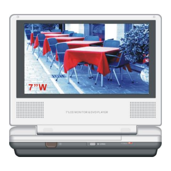
- Page 1 REV. (7.0-Inch) LCD Color Monitor & DVD Player MODEL : DPC-7200PD 2005/MAY...
-
Page 2: Table Of Contents
CONTENTS ---------------- Specification ............…..........…………….….. Block Diagram ........…..............…………….….. General Alignment Instruction ...............……….……..… Troubleshooting ...................…...……………...….. Printed Circuit Board ..................……………...…... IC Block Diagram and Lead Identification ............…………..….. Explode View ......................…………..…. Schematic Diagram ..................……………..….. -
Page 3: Specification
SPECIFICATION LCD MONITOR Model No.: LMD-4708GQU Out put: 50mW/16ohm Supply Voltage: Description Condition Unit Limit Nominal Headphone Output 1KHz 0dB 3±2 Headphone Noise No Signal <1mV <1mV 1KHz 0dB 600±100 SPK MAX Output 1KHz 0dB 600±100 1KHz 0dB 600±100 SPK MAX Output(AV IN) 1KHz 0dB 600±100 REF THD... - Page 4 Model No.: LMD-4708GQU Out put: 50mW/16ohm Supply Voltage: Description Condition Unit Limit Nominal Video Signal Level Vp-p 0.7±0.1 75% color SYNC Level Vp-p 0.3±0.1 bar/75ohm Video out level Vp-p 1.0±0.2 Video out level(Unload) 75% color bar Vp-p 2.0±0.2 1KHz/0dB/10K 2.0±0.2 Audio out level 2.0±0.2 1KHz/0dB/10K...
-
Page 5: Block Diagram
BLOCK DIAGRAM... -
Page 7: General Alignment Instruction
GENERAL ALIGNMENT INSTRUCTION The Main PCB of Monitor Modification: 1. Input voltage is 6.8V-16V, input signal is test circuit BY 5418. 2. Adjust VRT5 to get test point: 15720Hz.. 3. Adjust VRT4 to get horizontal phase shift. 4. Adjust VRT1 to get good performance. 5. -
Page 8: Troubleshooting
TROUBLESHOOTING SYMPTOM CAUSE REMEDY LCD MONITOR PART & Defective capacitor (C201) & Replace capacitor C201. 1) Picture distortion & Defective IC (IR3Y31). & Replace IC IR3Y31. 2) No Picture & Defective Q7, Q8. & Replace Q7, Q8. 3) No Picture, Picture no Good &... - Page 9 SYMPTOM CAUSE REMEDY DVD PART & Power source is not correct. & Replace power source. 1) No Power & Change the position of The positive and negative does not match the unit. positive and negative. & Power button defective. & Replace power button. &...
-
Page 10: Printed Circuit Board
PRINTED CIRCUIT BOARD Monitor Main PCB Top View -10-... - Page 11 Monitor Main PCB Bottom View -11-...
- Page 12 Battery Charger Circuit PCB Top View -12-...
- Page 13 Battery Charger Circuit PCB Bottom View -13-...
- Page 14 DVD Main PCB Top View -14-...
- Page 15 DVD Main PCB Bottom View -15-...
-
Page 16: Ic Block Diagram And Lead Identification
IC BLOCK DIAGRAM & DESCRIPTION IC IR3Y31 COMP SYNCSEP AGCDET BGP GEN AGC AMP PICTURE COMP VREF COMP CLAMP BRIGHT BRIGHT BRIGHT KILLER PHASE TINT SHIFT PAL SW IDENT FROM SYNC IN DEMOD MATRIX INT/EXT SW 41 40 39 IR3Y31 TRAP TINT SYNC OUT... - Page 17 IC BLOCK DIAGRAM & DESCRIPTION IC 8D02C 64 PIN FUNCTION DESCRIPTION - 1 Name Description Remark Power supply Note 1 Composite sync. Input pin Resolution mode setting pin 4 Note 2 Resolution mode setting pin 3 Note 2 Resolution mode setting pin 2 Note 2 Resolution mode setting pin 1 Note 2...
- Page 18 IC BLOCK DIAGRAM & DESCRIPTION IC 8D02C Name Description Remark H-POS position adjustment output signal H-POS position adjustment input signal Phase detect A output pin Control HSY & VSY pin for select I/O direction default=1 Oscillator output pin Oscillator input pin Master clock frequency divide by 2 function (FD2=0,/2) default=1 Connect capacitor to ground...
- Page 19 IC BLOCK DIAGRAM & DESCRIPTION IC 8D02C Vertical position adjustment for display area default=1 Power ON initialize; and UOB signal input Note 3 Power ON delay; VCO adjust can connect to GND. Note 4 Note 5 NTSC/PAL detect output & Control pin, NTSC=1, PAL=0 Note 6 Note 5 Gate 240=1 or 244=0 select pin...
- Page 20 IC BLOCK DIAGRAM & DESCRIPTION IC M5237 INPUT OUTPUT (V1) (V0) V IN Protrction CIRCUIT THERMAL PROTECTION CIRCUIT ADJUGT Voliage START Gemrator CIRCUIT CIRCUIT Oven-currfnt PROTECTION CIRCUIT GROUND PIN NAME V IN GROUND ADJUST IC RT9266 PIN NAME PIN NAME -20-...
- Page 21 IC BLOCK DIAGRAM & DESCRIPTION IC OZ970G 1=6uA 1=3uA Soft Start Irys. CTIMR COMP ACTIVE NDR_B NDR_B "HIGH" Protectlon Irys. COMP PDR_A PDR_A POFF IBIAS & POFF HF OSC Reference 2.75V OPLAMP Phase-Shift Controller PDR_C PDR_C NDR_D NDR_D PIN NAME PIN NAME NDR_D ENA ACTIVE “HIGH”...
- Page 22 IC BLOCK DIAGRAM & DESCRIPTION DVD IC 4558 NAME NAME -22-...
- Page 23 IC BLOCK DIAGRAM & DESCRIPTION AT24C02 START SERIAL STOP H.V. PUMP/TIMING CONTROL LOGIC LOGIC LOAD DATA RECOVERY COMP DEVICE ADDRESS COMPARATOR LOAD DATA WORD EEPROM ADDR/COUNTER Y DEC SERIAL MUX D out/ACK LOGIC V C C S C L S D A A T 2 4 C 0 2 G N D -23-...
- Page 24 IC BLOCK DIAGRAM & DESCRIPTION U9 MBM29F800TA LOGIC SYMBOL -24-...
- Page 25 IC BLOCK DIAGRAM & DESCRIPTION U9 MBM29F800TA Pin Name Function A-1, A18 to A0 Address Inputs DQ15 to DQ0 Data Inputs/Outputs Chip Enable Output Enable Write Enable RY/BY Ready/Busy Output RESET Hardware Reset Pin/Temporary Sector Unprotection BYTE Selects 8-bit or 16-bit mode N.C.
- Page 26 IC BLOCK DIAGRAM & DESCRIPTION IC K4S641632 -26-...
- Page 27 IC BLOCK DIAGRAM & DESCRIPTION IC K4S641632 -27-...
- Page 28 IC BLOCK DIAGRAM & DESCRIPTION U2 TDA2822 + Vs LREE CONTROL 5,8,12,13 INPUT INPUT IN P U T + (2 ) IN P U T + (1 ) N .C . N .C . IN P U T - (2 ) IN P U T - (1 ) G N D G N D...
- Page 29 IC BLOCK DIAGRAM & DESCRIPTION U18 BA5954 THERMAL STAND VINFC STBY SHUT DOWN OET1 BIAS CFCerr1 7.5K V TK CFCerr2 OET2 CTKerr1 7.5K CTKerr2 7.5K V LD VOSL 7.5K VNFFC Pre GND DET AMP. DET AMP. VNFTK PGND PGND PGND PGND VOSL- VOLD-...
- Page 30 IC BLOCK DIAGRAM & DESCRIPTION U18 BA5954FM Pin No. Pin name Function VINFC Focus drive input CFC err1 For connection of capacitor for the error amp filter CFC err2 For connection of capacitor for the error amp filter VINSL + Op-amp input (+) for the sled driver VINSL - Op-amp input (-) for the sled driver...
-
Page 31: Explode View
EXPLODED VIEW -31-... -
Page 32: Schematic Diagram
SCHEMATIC DIAGRAMS MONITOR PART MONITOR MAIN BOARD R252 R253 +9V ~+12V R236 680K R579 100K R238 C215 1uF/50V 330K +9V ~ +12V R240 R231 R232 C217 1uF/50V +9V ~ +12V R242 C234 R577 100K C219 1uF/50V C203 C232 0.01uF 1200P R233 18uH C227... - Page 33 MONITOR PART MONITOR MAIN BOARD CON? TO: PAGE 1 of 4 CON30 RT7 2K RT36 10 0 RT37 10 0 R T8 OPEN FRPT RT38 10 0 R T9 OPEN RT39 10 0 RT10 OPEN FRDV RT40 FRDV 10 0 VDD1 VDD1 OPEN...
- Page 34 MONITOR PART MONITOR HV BOARD 10 0UH 1A 63V C N7 01 R H6 1 C H1 10 uF/16 V 5.6V 10 K FD8958A C H9 3 R H7 9 0.04 7uF C H1 C H1 08 47 uF C N7 82 10 P/3KV C H1 09 0.02 2uF...
- Page 35 BATTERY CHARGER CIRCUIT C ON1 FUSE 2 .5 A SMD TR 4 10 K JACK9 1u F SI23 07 SK34 0.1u F R 2 2K IN4 001 PIN9 C ON2 C ON3 B 118 4 R 20 B 118 4 FUSE 1 .2 5A SI23 07 C 11...
- Page 36 DVD Part DVD POWER [ 2,3,4,5,6,7 ] DV33 DV33 [2,3,4 ] EJS4708GQU(89C) [ 3 ] URST URST [ 2,3 ] R132 R135 OPEN OPEN ON/OFF_DCIN SW17 ON/OFF_DCIN ON/OFF_DC DCIN POWER_OFF POWER_ON SS14(SMD) R123 OPEN AV-IN/OUT_SW AV-IN/OUT_SW [ 6,7 ] ON/OFF_DCIN ON/OFF_DC FB(DIP) AO3407...
- Page 37 DVD RF JITFO C102 390pF JITFN RFVDD3 RFV33 R167 750k DV 33 100k DV 33 C100 C101 2200pF CB 1 DA CV DD3 0.1uF/N .C OPEN 0.1uF 0.01uF 2200pF R 81 680k OP O R175 A DIN CB 55 S 27M H z OP - 27pF 27pF...
- Page 38 DVD ROM & RAM SD33 DV33 DQ[0..15] [ 2 ] DQ[0..15] [ 2 ] MA[0..11] MA[0..11] CB46 CB40 BA[0..1] BA[0..1] [ 2 ] [ 2 ] DQM[0..1] DQM[0..1] 0.1uF 0.1uF 0.1uF 10uF/10V-0805 0.1uF [ 2 ] DCLK DCLK 47uF/16V DCKE DCKE [ 2 ] [ 2 ]...
- Page 39 DVD MUTE ON/OFF_DC 1N4148 [ 3 ] ACLK ACLK 1N4148 100uF/16V [ 3 ] ABCK ABCK [ 3 ] ALRCK ALRCK 3904 [ 3 ] ASDAT0 ASDAT0 3906 [1,2,3,4,6,7 ] 470/0805 MUTE_ON 10uF/16V 33x4 ASDAT0 SDAT0 4.3V ACLK SACLK ABCK SBCLK ALRCK SLRCK...
- Page 40 DVD AV MONITOR_Y(VIDEO) MONITOR_Y(VIDEO) [ 7 ] 2907 ON_DCIN DAC_L I/O_R AVCM I/O_L Y3/CVBS VOUT CVBS_IN/OUT ADCIN ON/OFF_DCIN DAC_R AVCM Y6/SY I/O_L I/O_L I/O_R I/O_R VIDEO_+5V AUDIO IN/OUT AVCM SC-A Y5/SC 47pF ON/OFF_+9V DCIN [ 1 ] ON/OFF_+9V LCD_ON/OFF VIDE O_+5V [ 1 ] LCD_ON/OFF ON-DCIN...
- Page 41 DVD AUDIO JACK DV33 DCIN 0.1uF/0805 ON/OFF_+9V SC-A MONITOR_C MONITOR_Y(VIDEO) MONITOR_C MONITOR_WIDE/NOR MONITOR_CONTROL TO MONITOR BOARD(1)CON1 AV-IN/OUT_SW AV-IN/OUT_SW [ 1,6 ] MONITOR_CONTROL AVIN/OUT_SW 3904 ON/OFF_+9V ON/OFF_+9V [ 6 ] [ 1,2,3,4,5,6 ] VIDEO_+5V VIDEO_+5V [ 6 ] SP_R MUTE_ON MUTE_ON [ 5 ] SP_L MONITOR_Y(VIDEO) MONITOR_Y(VIDEO) [ 6 ]...
- Page 42 MEMO...
Need help?
Do you have a question about the DPC-7200PD and is the answer not in the manual?
Questions and answers